


5-5
Chapter 5, FRONT PANEL OPERATION
ON
When the Demodulator Monitor is switched ON and the instrument is operating
in External Reference mode, the signal at the OSC OUT connector changes from
that of the internal oscillator to an analog representation of the drive from the
reference channel to the X output demodulator. The amplitude of this signal may
be controlled by the internal oscillator amplitude controls, but the internal
oscillator frequency control is inactive since the frequency is related to the
external reference.
If the harmonic mode is set to 1st, the signal at the OSC OUT connector will be
at the same frequency as the applied reference, but if set to 2nd or 3rd then the
output will be at two or three times the reference frequency respectively.
OFF
When the Demodulator Monitor is switched OFF the OSC OUT connector
functions as the output from the internal oscillator. The signal provided at it may
be adjusted both in amplitude and frequency using the instrument’s controls. This
is the most common setting.
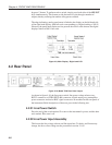
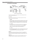
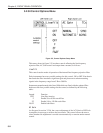
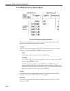
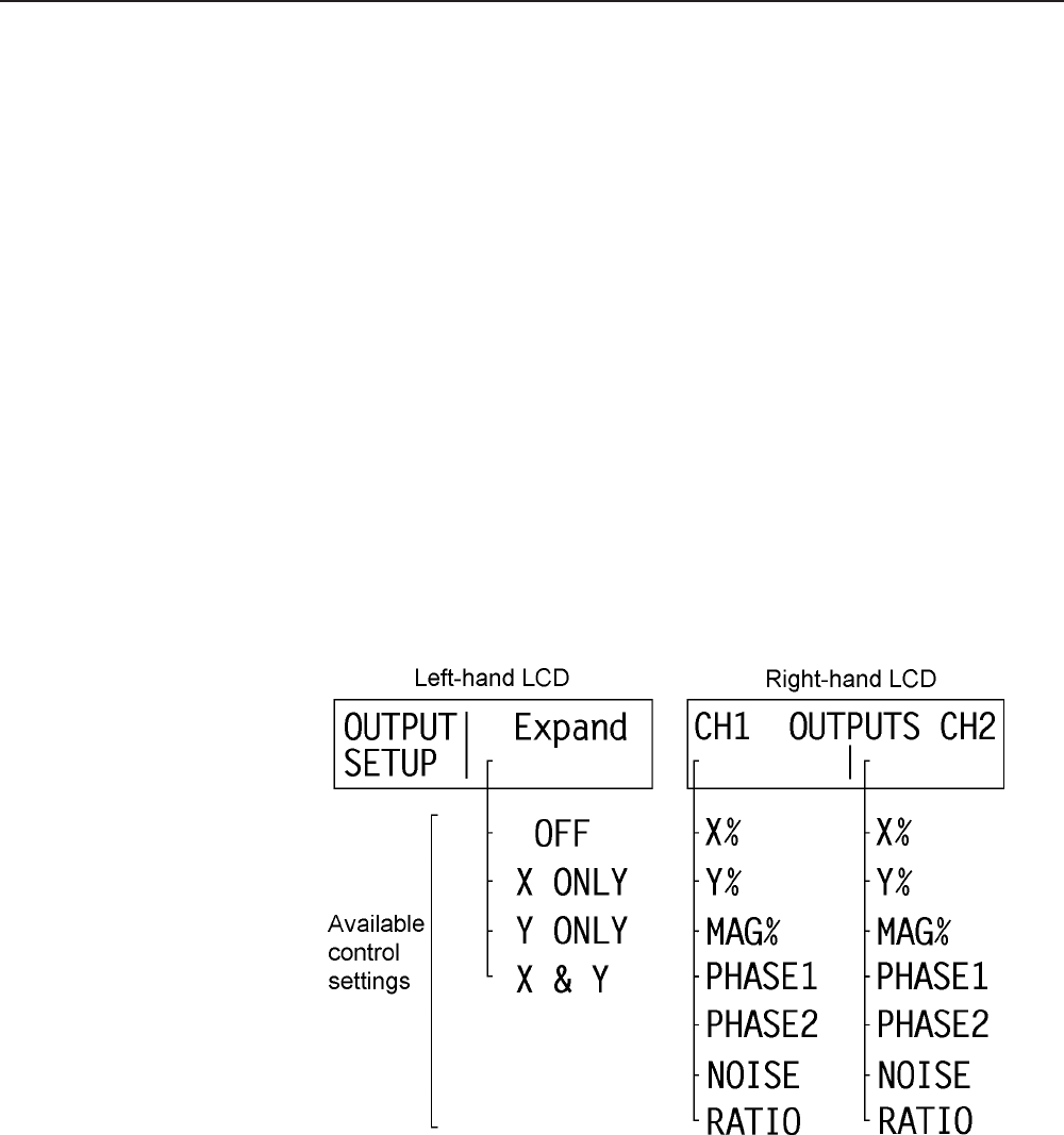
5.2.03 Output Setup Menu
Figure 5-4, Output Setup Menu
This menu, shown in figure 5-4, has three controls affecting the output channels of
the instrument. They are:-
Expand
This control allows a ×10 output expansion to be applied to the X, Y or both output
channels, or to be switched off:-