


5-2
Chapter 5, FRONT PANEL OPERATION
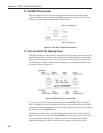
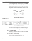
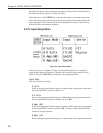
the right-hand display. The setup menu description is shown on the left-hand side of
the left-hand display. Figure 5-1 makes this clear.
One further press of the MENU key causes the instrument to leave the setup menu
mode and return to the main display mode. On leaving the setup menu mode the last
menu displayed is held in memory and will be displayed on re-entry. The following
sections describe each menu in sequence.
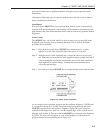
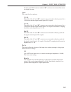
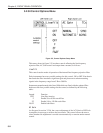
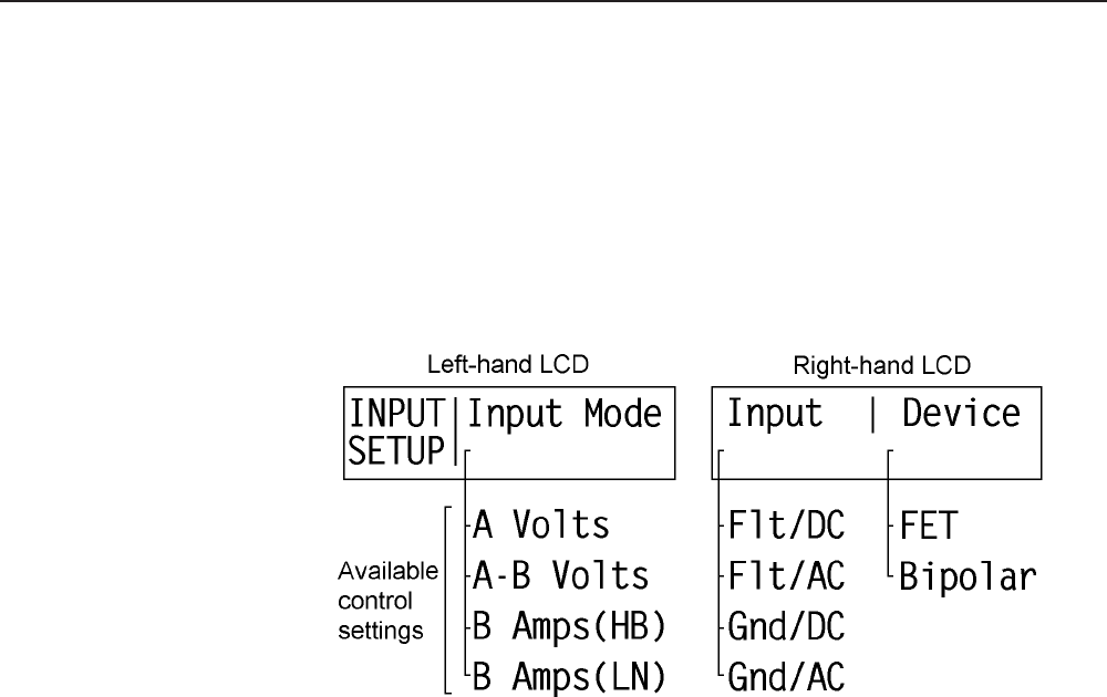
5.2.01 Input Setup Menu
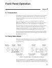
Figure 5-2, Input Setup Menu
In this menu, shown in figure 5-2, three controls affecting the lock-in amplifier’s
signal channel input are displayed. Changes to the setting of these controls can be
made by using the ADJUST keys adjacent to the appropriate LCD.
Input Mode
This control has four settings:-
A Volts
In this setting the signal channel input is a single-ended voltage input connected to
the front panel BNC connector marked “A”.
A-B Volts
In this setting the signal channel input is a differential voltage input connected to
the front panel BNC connectors marked “A” and “B/I”.
B Amps (HB)
In this setting the signal channel input is a single-ended current input connected to
the front panel BNC connector marked “B/I”, and uses a high bandwidth (HB)
current to voltage converter.
B Amps (LN)
In this setting the signal channel input is a single-ended current input connected to