6-33
Chapter 6, COMPUTER OPERATION
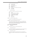
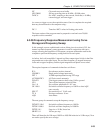
NC Clear and reset curve buffer
LEN 20000 500 ms recording time at 40 kHz = 20,000 points
TADC 6 Set ADC1 sampling to burst mode, fixed rate (≈ 40 kHz),
external trigger, and arm trigger
As soon as a trigger occurs, the acquisition starts. Once it completes the acquired
data may be transferred to the computer using:-
DC. 5 Transfers ADC1 values in floating point mode
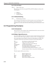
The input routine of the program must be prepared to read and store 20,000
responses to this command.
6.5.06 Frequency Response Measurement using Curve
Storage and Frequency Sweep
In this example, a more sophisticated version of that given in section 6.5.03, the
internal oscillator frequency sweep generator is used in conjunction with curve
storage, allowing the acquisition of a frequency response without the need for the
computer to perform the frequency setting function for each point.
As before, the lock-in amplifier’s internal oscillator output signal is fed via the filter
stage under test to the signal input. The oscillator frequency is stepped between a
lower and an upper frequency and the signal magnitude and phase are recorded.
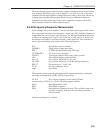
The required sequence of commands is therefore as follows:-
IE 0 Set reference mode to internal
VMODE 1 Single-ended voltage input mode
FET 1 10 MΩ input impedance using FET stage
AUTOMATIC 1 AC Gain control automatic
FLOAT 1 Float input connector shell using 1 kΩ to ground
LF 0 Turn off line frequency rejection filter
OA. 1.0 Set oscillator amplitude to 1.0 V rms
OF. 100.0 Set initial oscillator frequency to 100 Hz so that AQN
runs correctly
SEN 27 Set sensitivity to 1 V full-scale
TC 8 Set time constant to 10 ms
AQN Auto-Phase
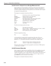
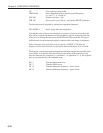
The next group of commands set up the frequency sweep:
FSTART. 100.0 Set initial oscillator frequency to 100 Hz
FSTOP. 1000.0 Set final oscillator frequency to 1000 Hz
FSTEP. 10 1 Step size = 10 Hz, linear law
SRATE. 0.1 100 ms per step
There will therefore be 100 steps (100 Hz to 1000 Hz inclusive in 10 Hz steps). Now
we need to specify the curve storage:


