


4-7
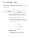
Chapter 4, FRONT AND REAR PANELS
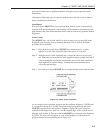
4.2.03 RS232 Connector
This 9-pin D type RS232 interface connector implements pins 1, 2, 3 and 7 (Earth
Ground, Transmit Data, Receive Data, Logic Ground) of a standard DTE interface.
To make a connection to a PC-compatible computer, it is normally sufficient to use a
three-wire cable connecting Transmit Data to Receive Data, Receive Data to
Transmit Data, and Logic Ground to Logic Ground. Appendix D shows the
connection diagrams of cables suitable for computers with 9-pin and 25-pin serial
connectors. Pinouts for this connector are given in appendix B.
4.2.04 AUX RS232 Connector
This connector is used to link other compatible EG&G equipment together in a
“daisy-chain” configuration. Up to an additional 15 units can be connected in this
way. Each unit must be set to a unique address (see section 5.2.08). Pinouts for this
connector are given in appendix B.
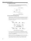
4.2.05 GPIB Connector
The GPIB interface connector conforms to the IEEE-488 1978 Instrument Bus
Standard. The standard defines all voltage and current levels, connector
specifications, timing and handshake requirements.
4.2.06 DIGITAL OUTPUTS Connector
This connector provides eight TTL output lines, each of which can be set high or low
by the use of a front panel setup menu or via the computer interfaces. It is most
commonly used for controlling auxiliary apparatus, such as lamps, shutters and
heaters. Pinouts for this connector are given in appendix B.
4.2.07 PREAMP POWER Connector
This connector supplies ±15 V at up to 100 mA and can be used for powering any of
several optional remote preamplifiers available from EG&G Instruments. Pinouts for
this connector are given in appendix B.
4.2.08 REF MON Connector
The signal at this connector is a TTL-compatible waveform synchronous with the
reference. This output monitors correct reference channel operation but its polarity is
not uniquely defined so that it does not necessarily show the correct phase
relationship with the SIG MON output.
4.2.09 REF TTL Connector
This connector is provided to allow TTL compatible pulses to be used as the
reference input.
4.2.10 SIG MON Connector
The signal at this connector is that immediately prior to the main analog to digital
converter and after the preamplifier, line filter and anti-alias filters.