


3-12
Chapter 3, TECHNICAL DESCRIPTION
The 6 dB/octave filters are not satisfactory for most purposes because they do not
give good rejection of periodic components in the demodulator output, including the
inevitable component at double the reference frequency. However, the 6 dB/octave
filter finds use where the lock-in amplifier is incorporated in a feedback control loop,
and in some situations where the form of the time-domain response is critical. The
user is recommended to use 12 dB/octave unless there is some definite reason for not
doing so.
Note that the filter slope for the rear panel FAST X and FAST Y outputs is fixed at
6 dB/octave.
3.8.02 Time Constants and Synchronization
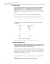
The output time constant can be varied between 10 µs and 5 ks. Values from 10 µs to
640 µs are available at the rear panel FAST X and FAST Y outputs, while values
from 5 ms to 5 ks apply to all other outputs, including CH1, CH2 and the digital
displays.
The filters are of the Finite Impulse Response (FIR) type with the averaging time of
each section being equal to double the nominal time constant.
These filters offer a substantial advantage in response time compared with analog
filters or digital Infinite Impulse Response (IIR) filters.
When the reference frequency is below 10 Hz the synchronous filter option is
available. This means that the actual time constant of the filter is not generally the
selected value T but a value which is equal to an integer number of reference cycles.
If T is greater than 1 reference cycle, the time constant is between T/2 and T.
Where random noise is relatively small, synchronous filter operation gives a major
advantage in low-frequency measurements by enabling the system to give a constant
output even when the output time constant is equal to only 1 reference cycle.
3.8.03 Output Offset and Expand
The output offset facility enables ±300 % full-scale offset to be applied to the X, Y or
both displays. Note however that the rear panel analog outputs limit at ±120 %
full-scale.
The output expand facility allows a ×10 expansion to be applied to the X, Y, both or
neither outputs, and hence to the analog meter indication and the CH1 and CH2
analog outputs, if these are set to output X or Y values.
3.9 Use of Magnitude and Signal Phase Outputs
If the input signal V
s
(t) is a reference frequency sinusoid of constant amplitude, and
the output filters are set to a sufficiently long time constant, the demodulator outputs
are constant levels V
x
and V
y
. The function √(V
x
2
+ V
y
2
) is dependent only on the
amplitude of the required signal V
s
(t) (i.e. it is not dependent on the phase of V
s
(t)