


5-35
Chapter 5, FRONT PANEL OPERATION
warning message OFFSET!
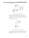
The instrument provides a quick way to switch between the following pairs of
outputs, by simply pressing simultaneously both ends of the SELECT keys adjacent
to their description:-
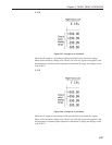
X %fs ↔ X volts or amps
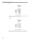
Y %fs ↔ Y volts or amps
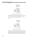
Mag %fs ↔ Mag volts or amps
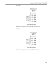
Noise %fs ↔ Noise volts/√Hz or amps/√Hz
5.6 Typical Lock-in Amplifier Experiment
Having discussed how the instrument’s controls may be adjusted and outputs
displayed, readers may find the following basic checklist helpful in setting up the
instrument for manual operation.
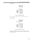
Auto-Default
Use the Auto-Default function on the Control Setup menu to set the instrument to a
known state.
Selection of Signal Input
Use the Input Setup menu to select voltage (single-ended or differential) or current
input mode, and connect your signal source to the relevant A and/or B/I input
connector(s).
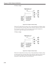
Selection of Reference Mode
The default setting function will have set the reference mode to internal, which
assumes that the internal oscillator will be used as a source of excitation to your
experiment. Use the Internal Oscillator amplitude and frequency controls to set the
required oscillator output, and connect the output signal from the OSC OUT
connector to your experiment.
If using external reference mode, use the Reference Setup menu to select one of the
two External modes, and connect your reference signal to the specified connector.
Auto-Measure
Use the Auto-Measure function to set the instrument so that it is correctly displaying
your signal.
Other Adjustments
You may now adjust the other controls as required, and choose the outputs you wish
to display. In particular, if you want to use the analog outputs of the instrument, use
the Output Setup menu to specify what the output signals at the CH1 and CH2
connectors should represent.