2-4
Chapter 2, INSTALLATION AND INITIAL CHECKS
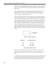
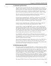
the CONTROL SETUP menu is displayed, which will look similar to the
following:-
Figure 2-3, Control Setup Menu
7) Press one of the keys on the right-hand side of the left-hand display once. This
will set all the instrument’s controls and displays to a known state. The displays
will revert to the normal mode, with the left-hand panel showing the AC Gain and
Full Scale Sensitivity controls and the right-hand one the instrument’s outputs in
the form of magnitude as a percentage of full-scale and phase in degrees.
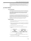
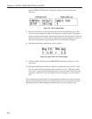
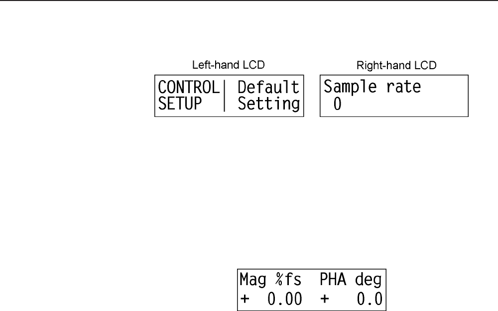
8) The right-hand display should now look as follows:-
Figure 2-4, Right-hand LCD - Main Display
9) Connect a BNC cable between the OSC OUT and A input connectors on the
front panel.
10) The right-hand display should now indicate a magnitude close to 100 % of full-
scale (i.e. the sinusoidal oscillator output, which was set to 1 kHz and a signal
level of 0.5 V rms by the Default Setting key is being measured with a full-scale
sensitivity of 500 mV rms) and a phase of near zero degrees, if a short cable is
used.
This completes the initial checks. Even though the procedure leaves many functions
untested, if the indicated results were obtained the user can be reasonably sure that
the unit incurred no hidden damage in shipment and is in good working order.


