E-20
Appendix E, ALPHABETICAL LISTING OF COMMANDS
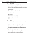
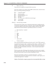
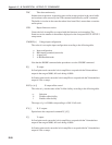
TDC Take data continuously
Initiates data acquisition. Acquisition starts at the current position in the curve buffer
and continues at the rate set by the STR command until halted by an HC command.
The buffer is circular in the sense that when it has been filled, current data overwrites
earlier points.
VER Report firmware version
Causes the lock-in amplifier to respond with the firmware version number. The
firmware version number is the number displayed on the front panel RS232 SETUP 3
setup screen.
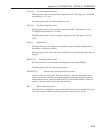
VMODE [n] Voltage input configuration
The value of n sets up the input configuration according to the following table:
n Input configuration
0 Both inputs grounded (test mode)
1 A input only
3 A-B differential mode
Note that the IMODE command takes precedence over the VMODE command.
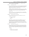
X[.] X output
In fixed point mode causes the lock-in amplifier to respond with the X demodulator
output in the range ±30000, full-scale being ±10000.
In floating point mode causes the lock-in amplifier to respond with the X demodulator
output in volts or amps.
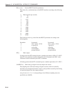
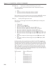
XOF [n
1
[n
2
]] X output offset control
The value of n
1
sets the status of the X offset facility according to the following table:
n
1
Selection
0 Disables offset facility
1 Enables offset facility
The range of n
2
is ±30000 corresponding to ±300 % full-scale.
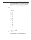
XY[.] X, Y outputs
Equivalent to the compound command X[.];Y[.]
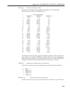
Y[.] Y output
In fixed point mode causes the lock-in amplifier to respond with the Y demodulator
output in the range ±30000, full-scale being ±10000.
In floating point mode causes the lock-in amplifier to respond with the Y demodulator
output in volts or amps.


