


5-4
Chapter 5, FRONT PANEL OPERATION
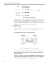
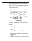
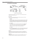
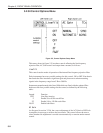
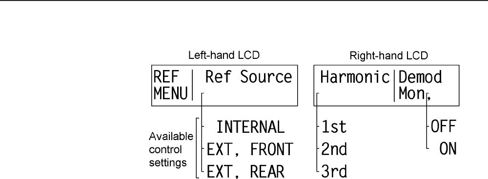
5.2.02 Reference Setup Menu
Figure 5-3, Reference Setup Menu
In this menu, shown in figure 5-3, there are three controls affecting the reference
channel of the instrument. They are:-
Ref Source
This control allows selection of the source of reference signal used to drive the
reference circuitry, and has three settings:-
INTERNAL
The lock-in amplifier’s reference is taken from the instrument’s internal oscillator.
Note that this setting gives the best phase and gain measurement accuracy under
all operating conditions, and is always to be preferred if it is possible to design
the experiment so that the lock-in amplifier acts as a source of reference signal.
EXT, FRONT
In this setting, suitable for use with reference frequencies above 300 mHz, the
lock-in amplifier’s reference should be applied to the front panel REF IN
connector. A wide variety of signal waveforms may be employed but at
frequencies lower than 1 Hz, square waveforms should be used.
EXT, REAR
In this setting, the lock-in amplifier’s reference should be applied to the rear panel
TTL compatible REF TTL connector. The use of this input is preferable to the
front panel input when a TTL logic reference signal is available.
Harmonic
This control allows selection of the harmonic at which the lock-in amplifier will
detect. It has three settings, but most commonly is set to “1st”. Note that the “2F”
setting found on other lock-in amplifiers corresponds to setting this control to “2nd”.
Demod Mon,
The Demodulator Monitor control has two settings, ON and OFF, which are only
meaningful when the lock-in amplifier is operated in external reference mode:-