


E-2
Appendix E, ALPHABETICAL LISTING OF COMMANDS
AXO Auto-Offset
The X and Y output offsets are turned on and set to levels giving zero X and Y
outputs. Any changes in the input signal then appear as changes about zero in the
outputs.
BURSTRATE [n] Sets the burst mode sampling rate for ADC1 and ADC2
n sets the sample rate for the Variable Rate burst modes according to the following
equations:
When storing only to ADC1:
(i.e. TADC 2, TADC 4, TADC 6 and TADC 8)
16,000,000
Sample Rate = ————— Hz
((25 × n) + 157)
When storing to ADC1 and ADC 2:
(i.e. TADC 3, TADC 5, TADC 7 and TADC 9)
16,000,000
Sample Rate = ————— Hz
((25 × n) + 1031)
Note that these equations apply only to units manufactured after December 1995.
Earlier instruments used a 16.384 MHz instead of a 16.0 MHz crystal, so the above
equations should be modified accordingly by replacing the 16,000,000 figure with
16,384,000.
For example when n = 20, the sample rate will be 24,353 Hz for ADC1 for an
instrument with a 16.0 MHz crystal, and 24,937 Hz for a unit with a 16.384 MHz
crystal.
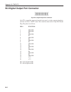
BYTE [n] Digital output port control
The value of n, in the range 0 to 255, determines the bits to be output on the rear
panel digital output port. When n = 0, all outputs are low, and when n = 255, all are
high.
CBD [n] Curve buffer define
Defines which data outputs are stored in the curve buffer when subsequent TD (take
data) or TDC (take data continuously) commands are issued. Up to 16 curves, or
outputs, may be acquired, as specified by the CBD parameter.
The CBD is an integer between 0 and 65,535, being the decimal equivalent of a 16-bit
binary word. When a given bit in the word is asserted, the corresponding output is
selected for storage. When a bit is negated, the output is not stored. The bit function
and range for each output are shown in the table below: