


4-6
Chapter 4, FRONT AND REAR PANELS
keypress” feature. To perform such a switch, simply press both sides of the SELECT
keys simultaneously. This feature avoids the need to cycle through a number of
outputs, thereby reducing the number of keypresses needed.
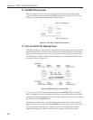
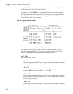
The edge-indicating, analog panel meter is linked to the display on the left-hand side
of the right-hand display, with full-scale corresponding to a digital reading of 100 %.
However, the panel meter limits at a few percent above full-scale whereas the digital
displays limit at ±300 % full-scale.
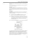
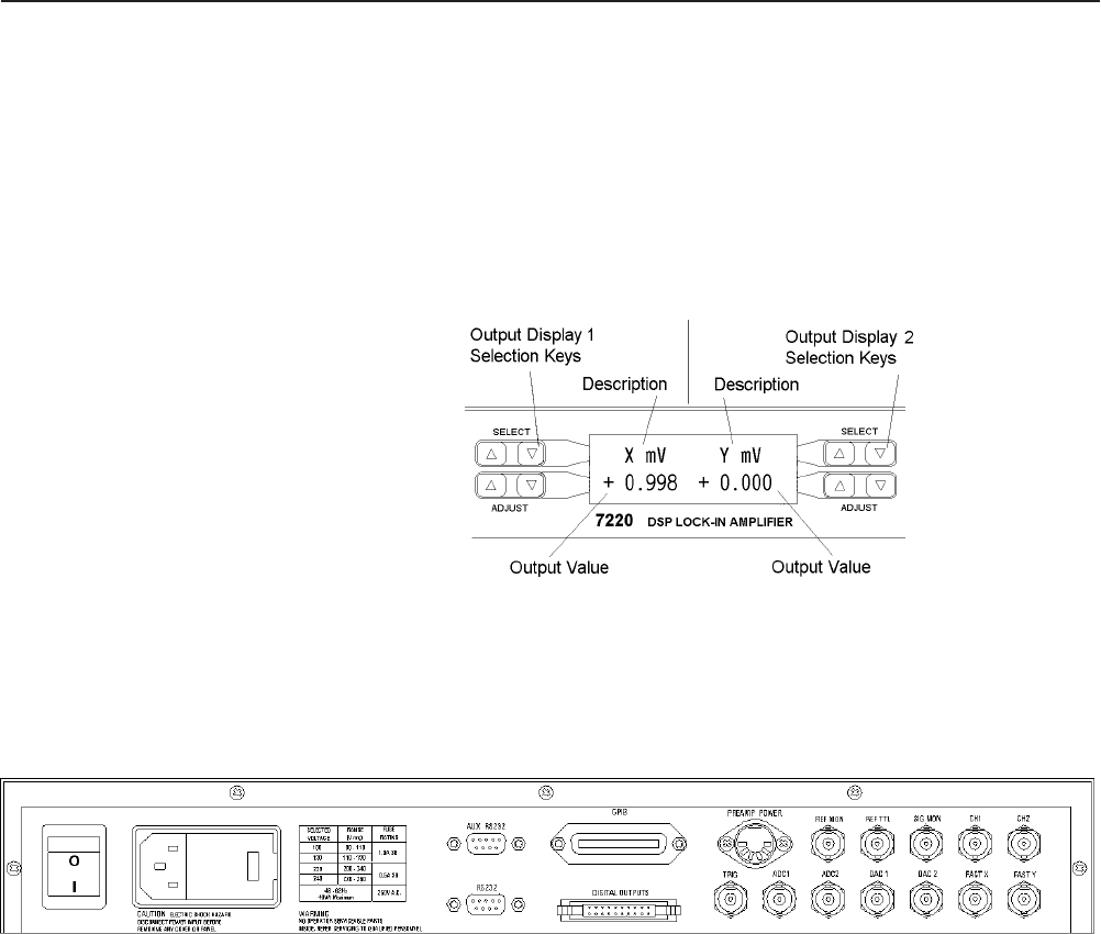
Figure 4-9, Main Display - Right-hand LCD
4.2 Rear Panel
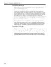
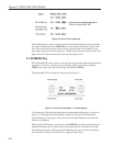
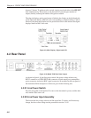
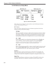
Figure 4-10, Model 7220 Rear Panel Layout
As shown in figure 4-10, the line power switch, line power voltage selector, two
RS232 connectors, a GPIB (IEEE-488) connector, digital output port, preamplifier
power connector and twelve BNC signal connectors are mounted on the rear panel of
the instrument. Brief descriptions of these are given in the following text.
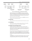
4.2.01 Line Power Switch
Press the end of the switch marked I to turn on the instrument’s power, and the other
end, marked O, to turn it off.
4.2.02 Line Power Input Assembly
This houses the line voltage selector and line input fuse. To check, and if necessary
change, the fuse or line voltage see the procedure in section 2.1.05.