6-31
Chapter 6, COMPUTER OPERATION
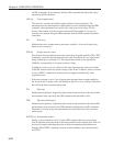
The controlling program would send a new output command each time a new reading
were required. Note that a good “rule of thumb” is to wait for a period of five time-
constants after the input signal has changed before recording a new value. Hence in a
scanning type experiment, the program should issue the commands to whatever
equipment causes the input signal to the lock-in amplifier to change, wait for five
time-constants, and then record the required output.
6.5.03 Frequency Response Measurement
In this example, the lock-in amplifier’s internal oscillator output signal is fed via the
filter stage under test back to the instrument’s signal input. The oscillator frequency is
stepped between a lower and an upper frequency and the signal magnitude and phase
recorded. At sampling rates of up to a few points per second, there is no need to use
the internal curve buffer or oscillator frequency sweep generator. The commands to
achieve this would therefore be similar to the following sequence:
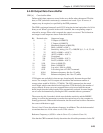
IE 0 Set reference mode to internal
VMODE 1 Single-ended voltage input mode
FET 1 10 MΩ input impedance using FET stage
AUTOMATIC 1 AC Gain control automatic
FLOAT 1 Float input connector shell using 1 kΩ to ground
LF 0 Turn off line frequency rejection filter
OA. 1.0 Set oscillator amplitude to 1.0 V rms
OF. 100.0 Set oscillator frequency to 100 Hz (starting frequency)
SEN 27 Set sensitivity to 1 V full-scale
TC 10 Set time constant to 50 ms
AQN Auto-Phase
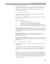
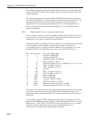
The frequency sweep would be performed and the outputs recorded by sending the
following commands from a FOR...NEXT program loop:
OF. XX Set oscillator frequency to new value XX hertz
software delay of 250 ms (5 × 50 ms) allowing output to stabilize
MAG. Read Magnitude in volts
PHA. Read Phase in degrees
FRQ. Read reference frequency in hertz. This would be same as the
oscillator frequency since the unit is operating in internal
reference mode.
until the stop frequency is reached.


