


6 - 3
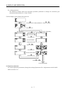
6. DISPLAY AND OPERATION
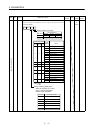
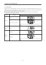
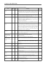
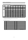
The following table lists the servo statuses that may be shown:
Name Symbol Unit Description
Display
Range
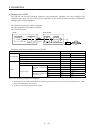
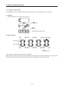
Cumulative feedback
pulses
C pulse Feedback pulses from the servo motor encoder are counted and
displayed. The value in excess of ±9999 is counted, bus since the
servo amplifier display is four digits, it shows the lower four digits of
the actual value. Press the "SET" button to reset the display value to
zero.
−9999
to
9999
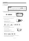
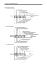
Servo motor speed r r/min The servo motor speed is displayed. When the servo motor is rotating
in the reverse direction, the decimal points in the upper 3 digits are
lit. The value rounded off is displayed in
×
0.1r/min.
−6000
to
6000
Droop pulses E pulse The number of droop pulses in the deviation counter is displayed.
When the servo motor is rotating in the reverse direction, the
decimal points in the upper 3 digits are lit.
Since the servo amplifier display is four digits, it shows the lower
four digits of the actual value.
The number of pulses displayed is not yet multiplied by the electronic
gear.
−9999
to
9999
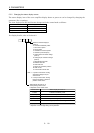
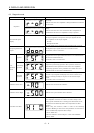
Cumulative command
pulses
P pulse The position command input pulses are counted and displayed. As
the value displayed is not multiplied by the electronic gear, it may
not match the indication of the cumulative feedback pulses. The
value in excess of ±9999 is counted, but since the servo amplifier
display is four digits, it shows the lower four digits of the actual
value. Press the "SET" button to reset the display value to zero.
When the servo motor is rotating in the reverse direction, the
decimal points in the upper 3 digits are lit.
−9999
to
9999
Command pulse
frequency
n kpps The frequency of the position command input pulses is displayed.
The value displayed is not multiplied by the electronic gear. When
the servo motor is rotating in the reverse direction, the decimal
points in the upper 3 digits are lit.
−500
to
500
Analog speed
command voltage
Analog speed limit
voltage
F V (1)Torque control mode
Analog speed limit (VLA) voltage is displayed.
(2)Speed control mode
Analog speed command (VC) voltage is displayed.
−10.00
to
10.00
(1)Position control mode, speed control mode
Reverse rotation analog torque limit (TLA) voltage is displayed.
−10
to
+10V
Analog torque
command voltage
Analog torque limit
voltage
UV
(2)Torque control mode
Reverse rotation analog torque command (TLA) voltage is
displayed.
0
to
+10V
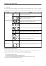
Regenerative load
ratio
L % The ratio of regenerative power to permissible regenerative power is
displayed in %.
0
to
100
Effective load ratio J %
The continuous effective load torque is displayed.
The effective value in the past 15 seconds is displayed relative to the
rated torque of 100%.
0
to
300
Peak load ratio b % The maximum torque generated during acceleration/deceleration,
etc.
The highest value in the past 15 seconds is displayed relative to the
rated torque of 100%.
0
to
400
Within one-revolution
position
Cy pulse Position within one revolution is displayed in encoder pulses.
The value returns to 0 when it exceeds the maximum number of
pulses.
The value is incremented in the CCW direction of rotation.
0
to
8191
Multi-revolution
counter
LS rev The value of the multi-revolution counter is displayed.
Since the servo amplifier display is four digits, it shows the lower
four digits of the actual value.
−32768
to
32767
Load inertia moment
ratio
dc 0.1
Times
The estimated ratio of the load inertia moment to the servo motor
shaft inertia moment is displayed.
0
to
1000