


3 - 43
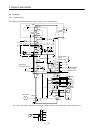
3. SIGNALS AND WIRING
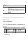
3.8 Servo Motor with Electromagnetic Brake
CAUTION
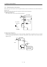
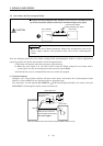
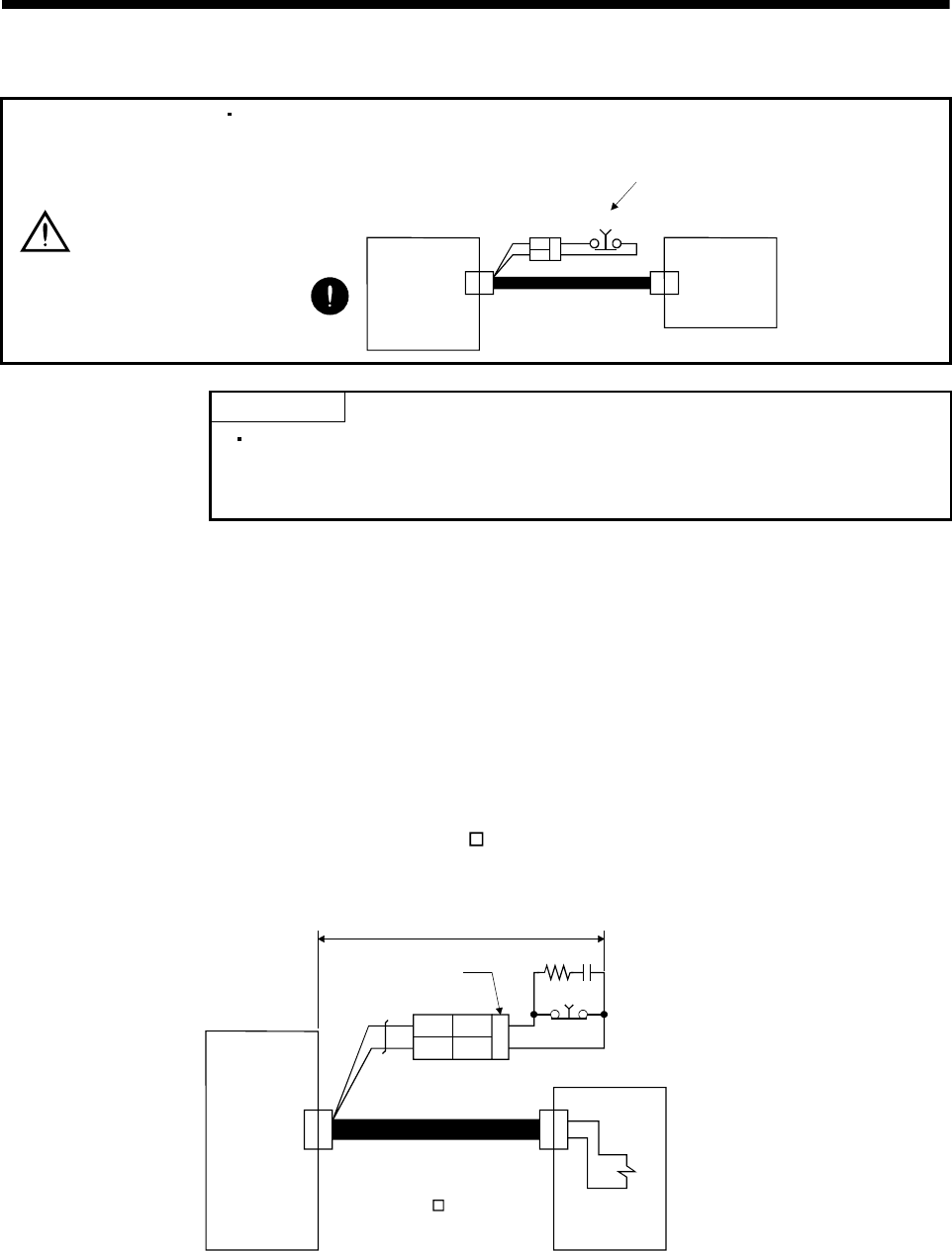
Configure the electromagnetic brake operation circuit so that it is activated not only
by the servo amplifier signals but also by an external emergency stop signal.
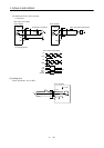
CNP2
EMG
Servo amplifier
Circuit must be opened
during emergency stop signal.
Servo motor
POINT
Refer to the Servo Motor Instruction Manual for specifications such as the
power supply capacity and operation delay time of the electromagnetic
brake.
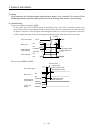
Note the following when the servo motor equipped with electromagnetic brake is used for applications
requiring a brake to hold the motor shaft (vertical lift applications):
1) The brake will operate when the emergency stop switch on.
2) While the reset signal is on, the base circuit is shut off. When using the servo motor with a
vertical shaft, use the electromagnetic brake interlock signal (MBR).
3) Switch off the servo-on command after the servo motor has stopped.
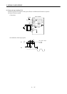
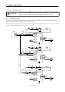
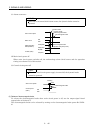
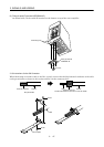
(1) Connection diagram
Configure up a circuit which switches off main circuit power and makes the electromagnetic brake
effective as soon as EMG-SG are disconnected at a emergency stop.
For connection, use the optional MR-JRBRCBL
M-H electromagnetic braked servo motor cable and
MR-JRBRCN electromagnetic brake contact connector set.
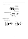
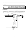
B1A 1
B1B
2
EMG
10m(32.8ft) or less
Servo amplifier
Connector set for electromagnetic
brake contact (option)
MR-JRBRCN
(Note)
CNP2
Servo motor
Cable for servo motor with
electromagnetic brake (option)
MR-JRBRCBL M-H
Note. Fit a snubber circuit to the forced stop contact. (Refer to Section 12.2.5)
CNP21