


3 - 18
3. SIGNALS AND WIRING
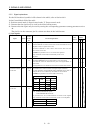
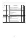
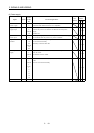
(3) Power supply
Control
Mode
Signal Symbol
Connec-
tor Pin
No.
Functions/Applications
I/O
Division
PST
I/F internal
power supply
VDD CN1B
3
Used to output 24VDC for input interface.
Connected with P24L inside the servo amplifier.
{{{
Digital I/F power
supply input
COM CN1A
9
CN1B
13
Used to input 24VDC for input interface.
Connect the positive terminal of the 24VDC external power
supply.
24VDC±10%
{{{
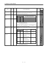
Open collector
power input
OPC CN1A
11
When inputting a pulse train in the open collector system, supply
this terminal with the positive (+) power of 24VDC.
{{{
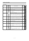
Digital I/F
common
SG CN1A
10
20
CN1B
10
20
Common terminal for input signals such as SON and EMG. Pins
are connected internally.
Internally connected with LG.
{{{
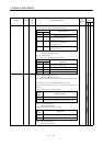
DC15V power
supply
P15R CN1A
4
CN1B
11
Outputs 15VDC to across P15R-LG. Available as power for TC,
TLA, VC, VLA.
Permissible current: 30mA
{{{
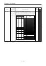
Control common LG CN1A
1
CN1B
1
CN3
1
3
5
11
13
15
Common terminal for TLA, TC, VC, VLA, FPA, FPB, OP and
P15R.
Pins are connected internally.
{{{
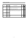
Shield SD Plate Connect the external conductor of the shield cable. {{{