


5 - 15
5. PARAMETERS
Class No. Symbol Name and Function
Initial
Value
Unit
Setting
Range
Control
Mode
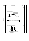
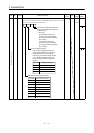
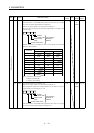
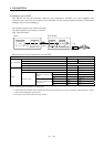
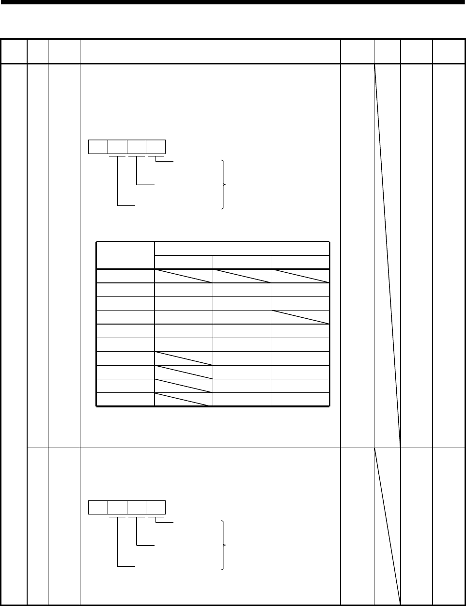
43 *DI2 Input signal selection 2 (CN1B-pin 5):
This parameter is unavailable when parameter No. 42 is set to assign
the control change signal (LOP) to CN1B-pin 5.
Allows any input signal to be assigned to CN1B-pin 5.
Note that the setting digit and assigned signal differ according to the
control mode.
0
Position
control mode
Input signals of
CN1B-pin 5
selected.
Torque control mode
Speed control
mode
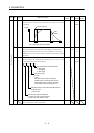
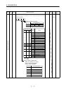
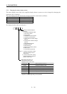
Signals that may be assigned in each control mode are indicated
below by their symbols.
Set value
(Note) Control Mode
PST
0
1
2
3
4
5
6
7
8
9
SON SON SON
RES RES RES
PC PC
TL TL TL
SP1 SP1
SP2 SP2
ST1 RS2
ST2 RS1
CR CR CR
Note. P: Position control mode
S: Speed control mode
T: Torque control mode
0111
0000h
to
0999h
P x S x T
Expansion parameters
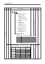
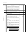
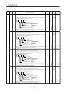
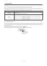
44 *DI3 Input signal selection 3 (CN1B-pin 14):
Allows any input signal to be assigned to CN1B-pin 14.
The assignable signals and setting method are the same as in input
signal selection 2 (parameter No. 43).
0
Position
control mode
Input signals of
CN1B-pin 14
selected.
Torque control mode
Speed control
mode
This parameter is unavailable when parameter No. 42 is set to assign
the control change signal (LOP) to CN1B-pin 14.
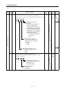
0222
0000h
to
0999h
P x S x T