


5 - 6
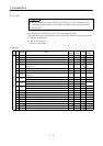
5. PARAMETERS
Class No. Symbol Name and Function
Initial
Value
Unit
Setting
Range
Control
Mode
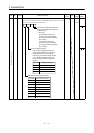
5 INP In-position range:
Used to set the droop pulse range in which the imposition (INP)
signal will be output.
100 pulse 0
to
10000
P
6 PG1 Position loop gain 1:
Used to set the gain of position loop 1.
Increase the gain to improve trackability in response to the position
command.
145 red/s 4
to
1000
P
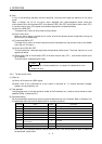
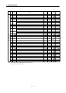
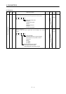
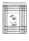
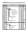
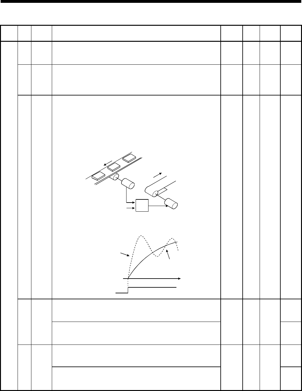
7 PST Position command acceleration/deceleration time constant
(smoothing):
Used to set the time constant of a low pass filter in response to the
position command.
Example: When a command is given from a synchronizing detector,
synchronous operation can be started smoothly if started during line
operation.
Synchronizing
detector
Start
Servo amplifier
Servo motor
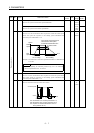
Without time
constant setting
Servo motor
speed
Start
With time
constant setting
ON
OFF
t
3ms0
to
20000
P
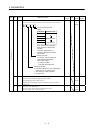
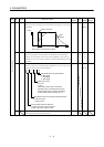
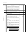
Internal speed command 1:
Used to set speed 1 of internal speed commands.
S8SC1
Internal speed limit 1:
Used to set speed 1 of internal speed limits.
100 r/min
0 to
instan-
taneous
permi-
ssible
speed
T
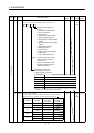
Internal speed command 2:
Used to set speed 2 of internal speed commands.
S
Basic parameters
9SC2
Internal speed limit 2:
Used to set speed 2 of internal speed limits.
500 r/min
0 to
instan-
taneous
permi-
ssible
speed
T