


3 - 27
3. SIGNALS AND WIRING
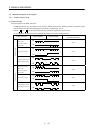
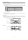
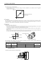
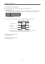
(b) Analog torque command offset
Using parameter No. 30, the offset voltage of -999 to +999mV can be added to the TC applied
voltage as shown below.
0
+8(−8)
Max. torque
Generated torque
TC applied voltage [V]
Parameter No.30 offset range
−999 to +999mV
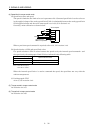
(2) Torque limit
By setting parameter No. 28 (internal torque limit 1), torque is always limited to the maximum value
during operation. A relationship between limit value and servo motor-generated torque is as in (2) in
section 3.4.1. Note that the analog torque limit (TLA) is unavailable.
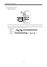
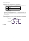
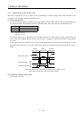
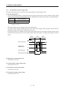
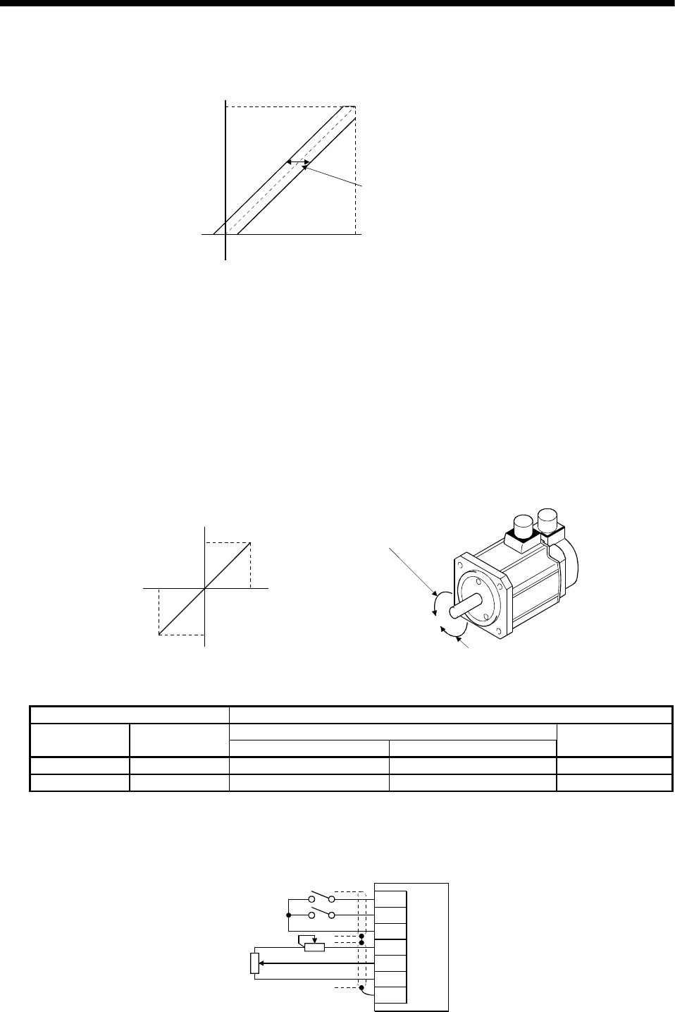
(3) Speed limit
(a) Speed limit value and speed
The speed is limited to the values set in parameters No. 8 to 10 (internal speed limits 1 to 3) or the
value set in the applied voltage of the analog speed limit (VLA).
A relationship between the analog speed limit (VLA) applied voltage and the servo motor speed is
shown below.
When the motor speed reaches the speed limit value, torque control may become unstable. Make the
set value more than 100r/min smaller than the desired speed limit value.
−10
0
+
10
Rated speed
Speed [r/min]
CCW direction
CW direction
VLA applied voltage [V]
Forward rotation (CCW)
Reverse rotation (CW)
Rated speed
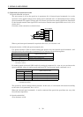
The following table indicates the limit direction according to forward rotation selection (RS1) and
reverse rotation selection (RS2) combination:
(Note) External Input Signals Speed Limit Direction
Analog Speed Limit (VLA)
RS1 RS2
+ Polarity − Polarity
Internal Speed
Commands
10 CCW CW CCW
01 CW CCW CW
Note. 0: RS1/RS2-SG off (open)
1: RS1/RS2-SG on (short)
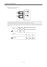
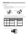
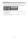
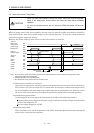
Generally, make connection as shown below:
SP1
SP2
SG
P15R
VC
LG
SD
2kΩ
2kΩ
Servo amplifier
Japan Resistor
RRS10 or equivalent