


3 - 7
3. SIGNALS AND WIRING
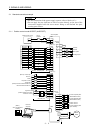
3.3 I/O Signals
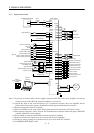
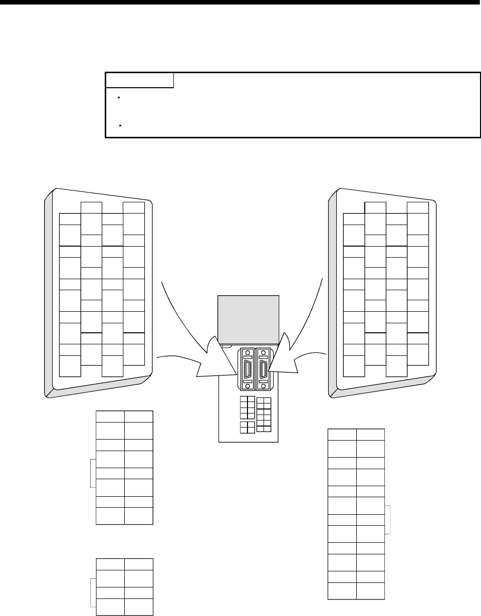
3.3.1 Connectors and signal arrangements
POINT
The pin configurations of the connectors are as viewed from the cable
connector wiring section.
Refer to the next page for CN1A and CN1B signal assignment.
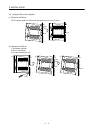
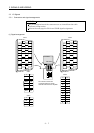
(1) Signal arrangement
The connector frames are
connected with the E (earth)
terminal inside the servo amplifier.
1
2
3
5
4
6
7
9
8
10
11
12
13
14
15
16
17
18
19
20
1
2
3
5
4
6
7
9
8
10
11
12
13
14
15
16
17
18
19
20
MITSUBISHI
MELSERVO
CN1A CN1B
51
RDP P24M
62
RDN P24G
73
SDP P24L
84
SDN TRE
CNP1
B2 B1
5
1
MR MRR
6
2
P5 LG
11
12
SD
104
7
3
UW
8
9
EV
CNP2
1
SD
2
TXD
LG
3
RXD
4
CNP3
CNP1
CNP3
CNP2