


5 - 3
5. PARAMETERS
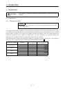
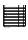
No. Symbol Name
Control
Mode
Initial
Value
Unit
Customer
Setting
20 *OP2 Function selection 2 P x S x T 0000
21 *OP3 Function selection 3 (Command pulse selection) P 0000
22 *OP4 Function selection 4 P x S x T 0000
23 FFC Feed forward gain P 0 %
24 ZSP Zero speed P x S x T50 r/min
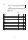
Analog speed command maximum speed S
(Note1) 0
(r/min)
25 VCM
Analog speed limit maximum speed T
(Note1) 0
(r/min)
26 TLC Analog torque command maximum output T 100 %
27 *ENR Encoder output pulses P x S x T 4000 pulse
28 TL1 Internal torque limit 1 P x S x T 100 %
Analog speed command offset S (Note2) mV
29 VCO
Analog speed limit offset T (Note2) mV
Analog torque command offset T 0 mV
30 TLO
Analog torque limit offset S 0 mV
31 For manufacturer setting 0
32 For manufacturer setting 0
33 MBR Electromagnetic brake sequence output P x S x T0 ms
34 GD2
Ratio of load inertia moment to servo motor inertia moment
P x S x T 3.0
0.1
times
35 PG2 Position loop gain 2 P 97 rad/s
36 VG1 Speed loop gain 1 P x S 873 rad/s
37 VG2 Speed loop gain 2 P x S 1144 rad/s
38 VIC Speed integral compensation P x S20ms
39 VDC Speed differential compensation P x S 980
40 For manufacturer setting 0
41 *DIA Input signal automatic ON selection P x S x T 0000
42 *DI1 Input signal selection 1 P x S x T 0003
43 *DI2 Input signal selection 2 (CN1B-pin 5) P x S x T 0111
44 *DI3 Input signal selection 3 (CN1B-pin 14) P x S x T 0222
45 *DI4 Input signal selection 4 (CN1A-pin 8) P x S x T 0665
46 *DI5 Input signal selection 5 (CN1B-pin 7) P x S x T 0770
47 *DI6 Input signal selection 6 (CN1B-pin 8) P x S x T 0883
48 *DI7 Input signal selection 7 (CN1B-pin 9) P x S x T 0994
Basic parameters
49 *DO1 Output signal selection 1 P x S x T 0000
Note 1. The setting of "0" provides the rated servo motor speed.
2. Depends on the servo amplifier.