


3 - 24
3. SIGNALS AND WIRING
3.4.2 Speed control mode
(1) Speed setting
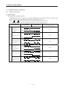
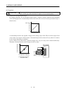
(a) Speed command and speed
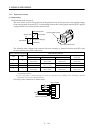
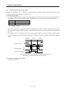
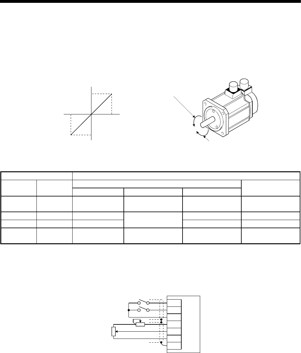
The servo motor is run at the speeds set in the parameters or at the speed set in the applied voltage
of the analog speed command (VC). A relationship between the analog speed command (VC) applied
voltage and the servo motor speed is shown below:
−
10
0
+
10
Rated speed [r/min]
Speed [r/min]
CW direction
VC applied voltage [V]
CCW direction
Rated speed
Forward rotation (CCW)
Reverse rotation (CW)
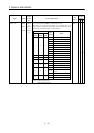
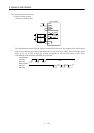
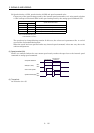
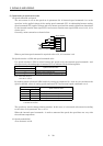
The following table indicates the rotation direction according to forward rotation start (ST1) and
reverse rotation start (ST2) combination:
(Note 1) External Input Signals (Note 2)Rotation Direction
Analog Speed Command (VC)
ST2 ST1
+ Polarity 0V − Polarity
Internal Speed
Commands
00
Stop
(Servo lock)
Stop
(Servo lock)
Stop
(Servo lock)
Stop
(Servo lock)
01 CCW CW CCW
10 CW
Stop
(No servo lock)
CCW CW
11
Stop
(Servo lock)
Stop
(Servo lock)
Stop
(Servo lock)
Stop
(Servo lock)
Note 1. 0: ST1/ST2-SG off (open)
1: ST1/ST2-SG on (short)
2. If the torque limit is canceled during servo lock, the servomotor may suddenly rotate according to position
deviation in respect to the command position.
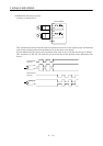
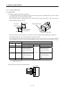
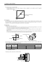
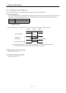
Generally, make connection as shown below:
SP1
SP2
SG
P15R
VC
LG
SD
2kΩ
2kΩ
Servo amplifier
Japan Resistor
RRS10 or equivalent