


5 - 9
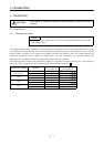
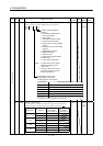
5. PARAMETERS
Class No. Symbol Name and Function
Initial
Value
Unit
Setting
Range
Control
Mode
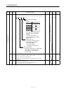
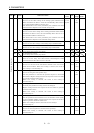
18
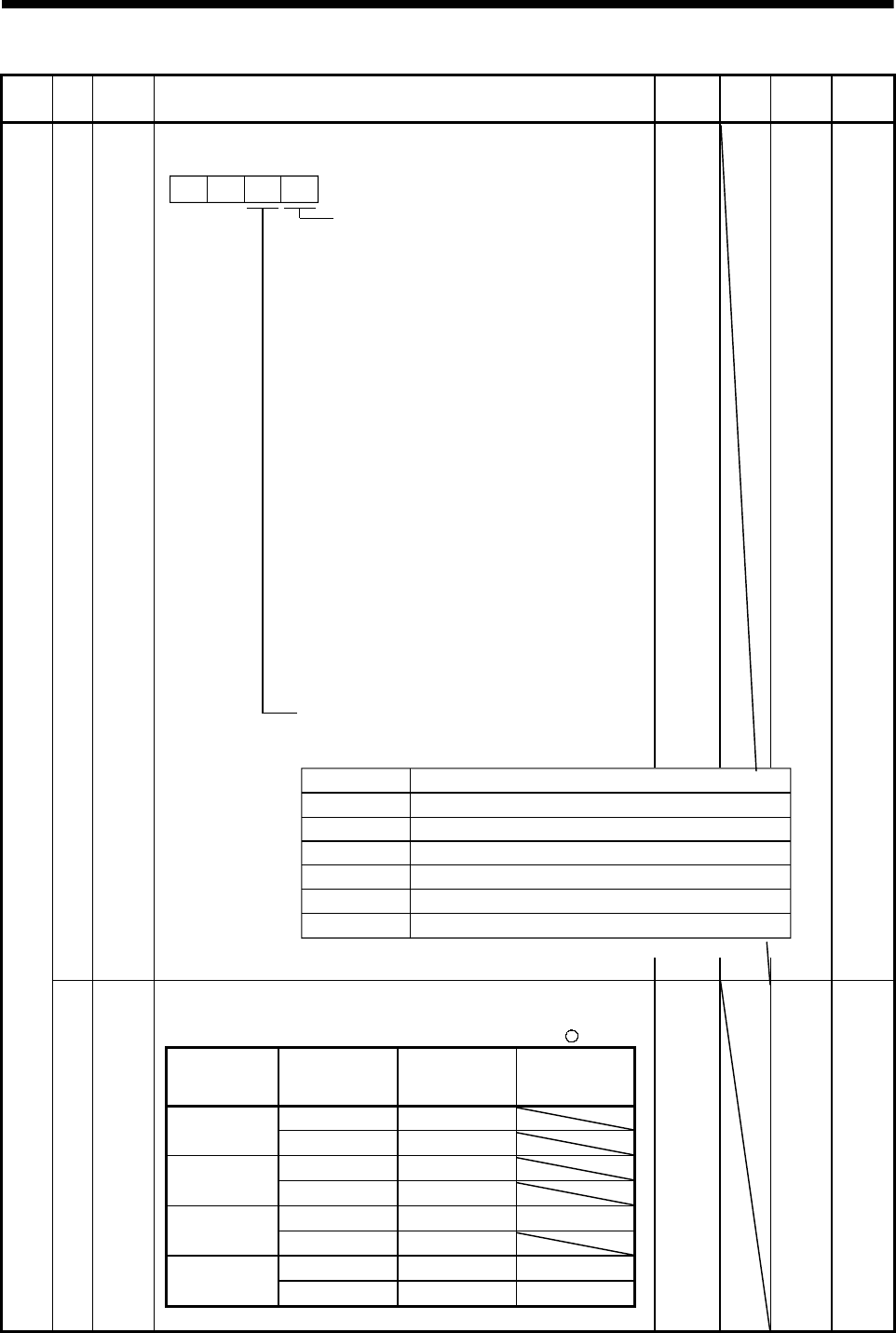
*DMD
Status display selection:
Used to select the status display shown at power-on.
Selection of status display at
power-on
0: Cumulative feedback pulses
1: Servo motor speed
2: Droop pulses
3: Cumulative command pulses
4: Command pulse frequency
5: Analog speed command voltage
(Note 1)
6: Analog torque command voltage
(Note 2)
7: Regenerative load ratio
8: Effective load ratio
9: Peak load ratio
A: Within one-revolution position
B: ABS counter
C: Load inertia moment ratio
00
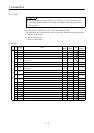
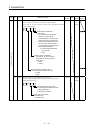
In speed control mode. Analog
speed limit voltage in torque
control mode.
In torque control mode. Analog
torque limit voltage in speed or
position control mode.
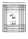
Note: 1.
2.
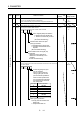
Status display at power-on in
corresponding control mode
0: Depends on the control mode.
0000 0000h
to
001Ch
P x S x T
Control Mode
Position
Position/speed
Speed
Speed/torque
Torque
Torque/position
Status Display at Power-On
Cumulative feedback pulses
Cumulative feedback pulses/servo motor speed
Servo motor speed
Servo motor speed/analog torque command voltage
Analog torque command voltage
Analog torque command voltage/cumulative feedback pulses
1: De
p
ends on the first di
g
it settin
g
of this
p
arameter.
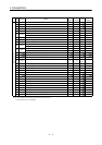
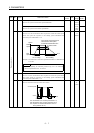
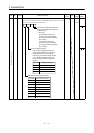
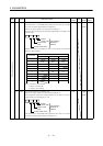
Parameter write inhibit:
Used to select the reference and write ranges of the parameters.
Operation can be performed for the parameters marked
.
Set Value Operation
Basic
Parameters
No. 0 to No. 19
Expansion
Parameters
No. 20 to No. 49
Reference
{
0000
(Initial value)
Write
{
Reference No. 19 only
000A
Write No. 19 only
Reference
{{
000B
Write
{
Reference
{{
000C
Write
{{
Basic parameters
19 *BLK 0000 0000h
to
000Ch
P x S x T