


3 - 17
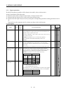
3. SIGNALS AND WIRING
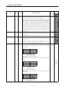
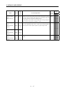
Control
Mode
Signal Symbol
Connec-
tor Pin
No.
Functions/Applications
I/O
Division
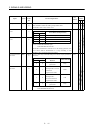
PST
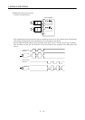
Encoder Z-phase
pulse
(Open collector)
OP CN1A
14
Outputs the zero-point signal of the encoder. One pulse is output
per servo motor revolution. OP and LG are connected when the
zero-point position is reached. ( Negative logic)
The maximum pulse width is about 400µs. For zeroing using this
pulse, set the creep speed to 100r/min. or less.
DO−2
{{{
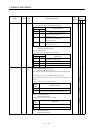
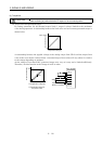
Encoder A-phase
pulse
(Differential line
driver)
LA
LAR
CN1A
6
CN1A
16
Encoder B-phase
pulse
(Differential line
driver)
LB
LBR
CN1A
7
CN1A
17
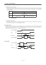
Outputs pulses per servo motor revolution set in parameter No.
27 in the differential line driver system. The encoder B-phase
pulse lags the encoder A-phase pulse by a phase angle of π/2.
DO−2
{{{
Encoder Z-phase
pulse
(Differential line
driver)
LZ
LZR
CN1A
5
CN1A
15
The same signal as OP is output in the differential line driver
system.
DO−2
{{{