


12 - 5
12. OPTIONS AND AUXILIARY EQUIPMENT
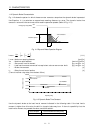
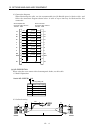
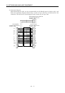
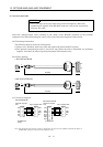
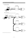
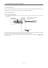
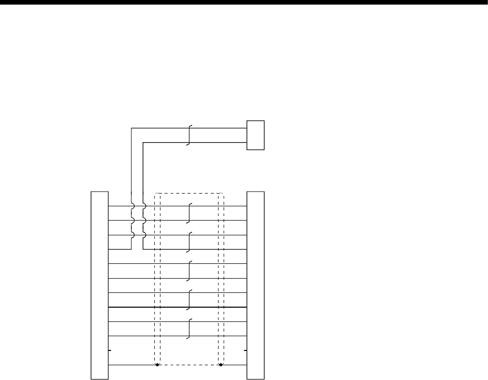
3) Connection diagram
When fabricating the cable, use the recommended wire (J14B1180) given in Section 12.2.1 and
follow the connection diagram shown below. A cable of up to 30m may be fabricated for this
connection. The cable for an electromagnetic brake contact may be up to 10m.
11LG
5P5
3B2
9B1
2U
7V
8W
1E
6MR
12MRR
10
4SD
0.5mm
2
0.5mm
2
0.3mm
2
0.3mm
2
0.5mm
2
0.5mm
2
0.5mm
2
0.5mm
2
0.2mm
2
0.2mm
2
11
5
3
9
2
7
8
1
6
12
10
4
LG
P5
B2
B1
U
V
W
E
MR
MRR
SD
Connector: 5557-12R-210
Terminal : 5556
Connector: 5559-12P-210
Terminal : 5558
Servo amplifier Servo motor side
B1B
1B1A
2
Connector: 5559-02P-210
Terminal : 5558
Electromagnetic brake contact side
Blue
Orange
Yellow
White
Red
White
Black
Green
Brown
White
Blue
Orange
Yellow
White
Red
White
Black
Green
Brown
White