


3 - 10
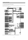
3. SIGNALS AND WIRING
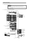
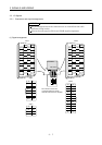
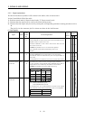
3.3.2 Signal explanations
For the I/O interfaces (symbols in I/O column in the table), refer to Section 3.6.2.
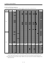
In the Control Mode field of the table
P : Position control mode, S: Speed control mode, T: Torque control mode
{: Denotes that the signal may be used in the initial setting status.
∆
: Denotes that the signal may be used by setting the corresponding parameter among parameters 43 to
49.
The pin No.s in the connector pin No. column are those in the initial status.
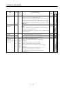
(1) Input signals
Control
Mode
Signal Symbol
Connec-
tor Pin
No.
Functions/Applications
I/O
Division
PST
Servo-on SON CN1B
5
Ready signal input terminal.
Connect SON-SG to switch on the base circuit and make the servo
amplifier ready to operate (servo on).
Disconnect SON-SG to shut off the base circuit and coast the
servo motor (servo off) .
Set1 in parameter No. 41 to switch this signal on
(keep terminals connected) automatically in the servo
amplifier.
DI-1
{{{
Reset RES CN1B
14
Alarm reset signal input terminal.
Disconnect RES-SG for more than 50ms to reset the alarm.
Some alarms cannot be deactivated by the reset signal. Refer to
Section 9.2.
Turning RES on in an alarm-free status shuts off the base circuit.
DI-1
{{{
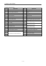
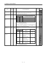
Forward/reverse rotation stroke end signal input terminals.
To start operation, short LSP-SG and/or LSN-SG. Open them to
bring the motor to a sudden stop and make it servo-locked.
Set1 in parameter No. 22 to make a slow stop.
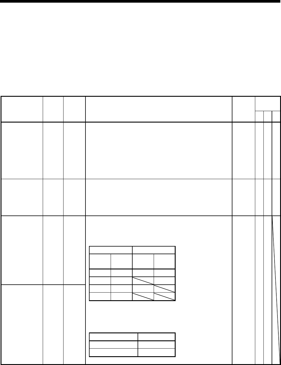
(Note) Input signals Operation
LSP LSN
CCW
direction
CW
direction
11{{
Forward rotation
stroke end
LSP CN1B
16
01 {
10{
00
Note. 0: OFF (LSP/LSN-SG open)
1: ON (LSP/LSN-SG shorted)
Set parameter No. 41 as indicated below to switch on the signals
(keep terminals connected) automatically in the servo amplifier:
Parameter No.41 Automatic ON
1 LSP
1 LSN
Reverse rotation
stroke end
LSN CN1B
17
DI-1
{{