


3 - 15
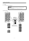
3. SIGNALS AND WIRING
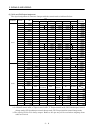
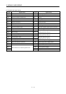
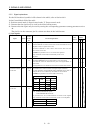
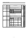
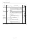
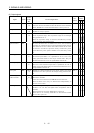
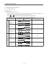
(2) Output signals
Control
Mode
Signal Symbol
Connec-
tor Pin
No.
Functions/Applications
I/O
Division
PST
Trouble ALM CN1B
18
ALM-SG are disconnected when power is switched off or the
protective circuit is activated to shut off the base circuit. Without
alarm, ALM-SG are connected within about 1s after power on.
DO−1
{{{
Ready RD CN1A
19
RD-SG are connected when the servo is switched on and the servo
amplifier is ready to operate.
DO−1
{{{
In position INP INP-SG are connected when the number of droop pulses is in the
preset in-position range. The in-position range can be changed
using parameter No. 5.
When the in-position range is increased, INP-SG may be kept
connected during low-speed rotation.
DO−1
{
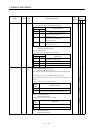
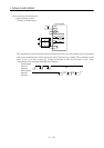
Speed reached SA
CN1A
18
SA turns off when servo on (SON) turns off or the servomotor
speed has not reached the preset speed with both forward rotation
start (ST1) and reverse rotation start (ST2) turned off. SA turns
on when the servomotor speed has nearly reached the preset
speed. When the preset speed is 20r/min or less, SA always turns
on.
DO−1
{
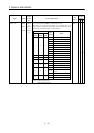
Limiting speed VLC CN1B
6
VLC-SG are connected when speed reaches the value set to any of
the internal speed limits 1 to 3 (parameters No. 8 to 10) or the
analog speed limit (VLA) in the torque control mode. They are
disconnected when the servo-on signal (SON) switches off.
DO−1
{
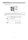
Limiting torque TLC CN1B
6
TLC-SG are connected when the torque generated reaches the
value set to the internal torque limit 1 (parameter No. 28) or
analog torque limit (TLA). They are disconnected when the servo-
on signal (SON) switches off.
DO−1
{{
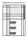
Zero speed ZSP CN1B
19
ZSP-SG are connected when the servo motor speed is zero speed
(50r/min) or less. Zero speed can be changed using parameter No.
24.
DO−1
{{{
Electromagnetic
brake interlock
MBR
CN1B
19
Set1 in parameter No. 1 to use this parameter. Note that
ZSP will be unusable.
In the servo-off or alarm status, MBR-SG are disconnected.
When an alarm occurs, they are disconnected independently of
the base circuit status.
DO−1
∆∆∆
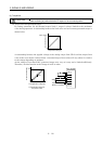
Warning WNG To use this signal, assign the connector pin for output using
parameter No. 49. The old signal before assignment will be
unusable.
When warning has occurred, WNG-SG are connected.
When there is no warning, WNG-SG are disconnected within
about 1s after power-on.
DO−1
∆∆∆