


5 - 16
5. PARAMETERS
Class No. Symbol Name and Function
Initial
Value
Unit
Setting
Range
Control
Mode
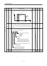
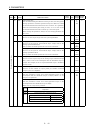
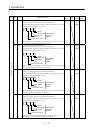
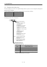
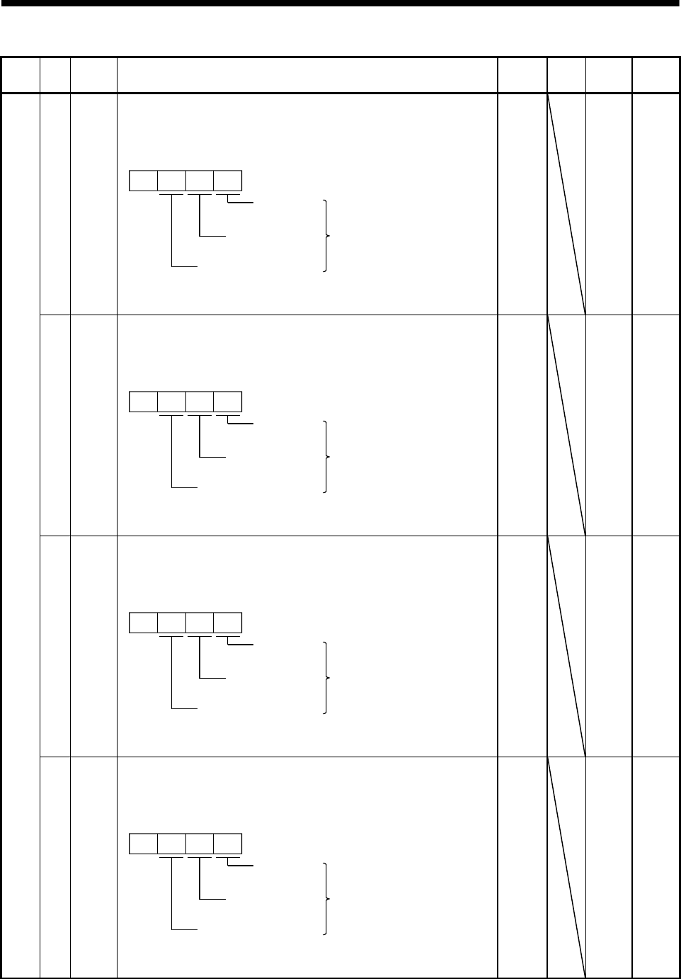
45 *DI4 Input signal selection 4 (CN1A-pin 8):
Allows any input signal to be assigned to CN1A-pin 8.
The assignable signals and setting method are the same as in input
signal selection 2 (parameter No. 43).
0
Position
control mode
Input signals of
CN1A-pin 8
selected.
Torque control mode
Speed control
mode
This parameter is unavailable when parameter No. 42 is set to assign
the control change signal (LOP) to CN1 A-pin 8.
0665
0000h
to
0999h
P x S x T
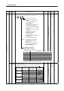
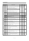
46 *DI5 Input signal selection 5 (CN1B-pin 7):
Allows any input signal to be assigned to CN1B-pin 7.
The assignable signals and setting method are the same as in input
signal selection 2 (parameter No. 43).
0
Position
control mode
Input signals of
CN1B-pin 7
selected.
Torque control mode
Speed control
mode
This parameter is unavailable when parameter No. 42 is set to assign
the control change signal (LOP) to CN1 B-pin 7.
0770
0000h
to
0999h
P x S x T
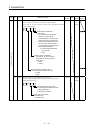
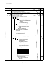
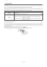
47 *DI6 Input signal selection 6 (CN1B-pin 8):
Allows any input signal to be assigned to CN1B-pin 8.
The assignable signals and setting method are the same as in input
signal selection 2 (parameter No. 43).
0
Position
control mode
Input signals of
CN1B-pin 8
selected.
Torque control mode
Speed control
mode
This parameter is unavailable when parameter No. 42 is set to assign
the control change signal (LOP) to CN1B-pin 8.
0883
0000h
to
0999h
P x S x T
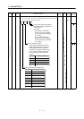
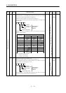
Expansion parameters
48 *DI7 Input signal selection 7 (CN1B-pin 9):
Allows any input signal to be assigned to CN1B-pin 9.
The assignable signals and setting method are the same as in input
signal selection 2 (parameter No. 43).
0
Position
control mode
Input signals of
CN1B-pin 9
selected.
Torque control mode
Speed control
mode
This parameter is unavailable when parameter No. 42 is set to
assign the control change signal (LOP) to CN1B-pin 9.
0994
0000h
to
0999h
P x S x T