


12 - 4
12. OPTIONS AND AUXILIARY EQUIPMENT
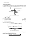
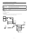
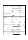
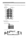
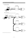
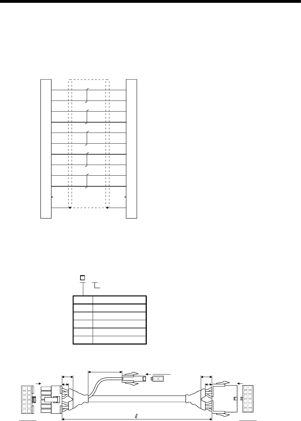
3) Connection diagram
When fabricating the cable, use the recommended wire (J14B1180) given in Section 12.2.1 and
follow the connection diagram shown below. A cable of up to 30m may be fabricated for this
connection.
11
5
3
9
2
7
8
1
6
12
10
4
11
5
3
9
2
7
8
1
6
12
10
4
LG
P5
B2
B1
U
V
W
E
MR
MRR
SD
LG
P5
B2
B1
U
V
W
E
SD
MR
MRR
0.5mm
2
0.5mm
2
0.3mm
2
0.3mm
2
0.5mm
2
0.5mm
2
0.5mm
2
0.5mm
2
0.2mm
2
0.2mm
2
Blue
Orange
Yellow
White
Red
White
Black
Green
Brown
White
Servo motor side
Connector: 5559-12P-210
Terminal :5558
Servo amplifier side
Connector: 5557-12R-210
Terminal :5556
Blue
Orange
Yellow
White
Red
White
Black
Green
Brown
White
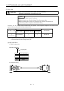
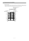
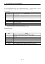
(b) MR-JRBRCBLM-H
When using the servo motor with electromagnetic brake, use this cable.
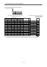
1) Model explanation
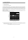
Symbol Cable Length [m]([ft])
2
5
10
20
30
2(6.5)
5(16.4)
10(32.8)
20(65.6)
30(98.4)
Long flexing life
Model: MR-JRBRCBL M-H
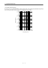
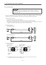
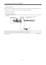
2) Outline drawing
12 11
65
10 9
43
87
21
1211
65
109
43
87
21
2
1
C
5
15
B
A
View C
200
5
15
View B
View A