


7 - 3
7. ADJUSTMENT
7.2 Gain Adjustment
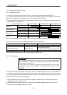
7.2.1 Parameters required for gain adjustment
Parameter No. Symbol Name
No. 2 ATU Auto tuning
No. 6 PG1 Position loop gain 1
No. 22 *OP4 Function selection 4 (machine resonance filter)
No. 34 GD2 Ratio of load inertia moment to motor inertia moment
No. 35 PG2 Position loop gain 2
No. 36 VG1 Speed loop gain 1
No. 37 VG2 Speed loop gain 2
No. 38 VIC Speed integral compensation
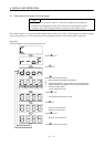
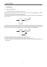
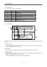
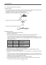
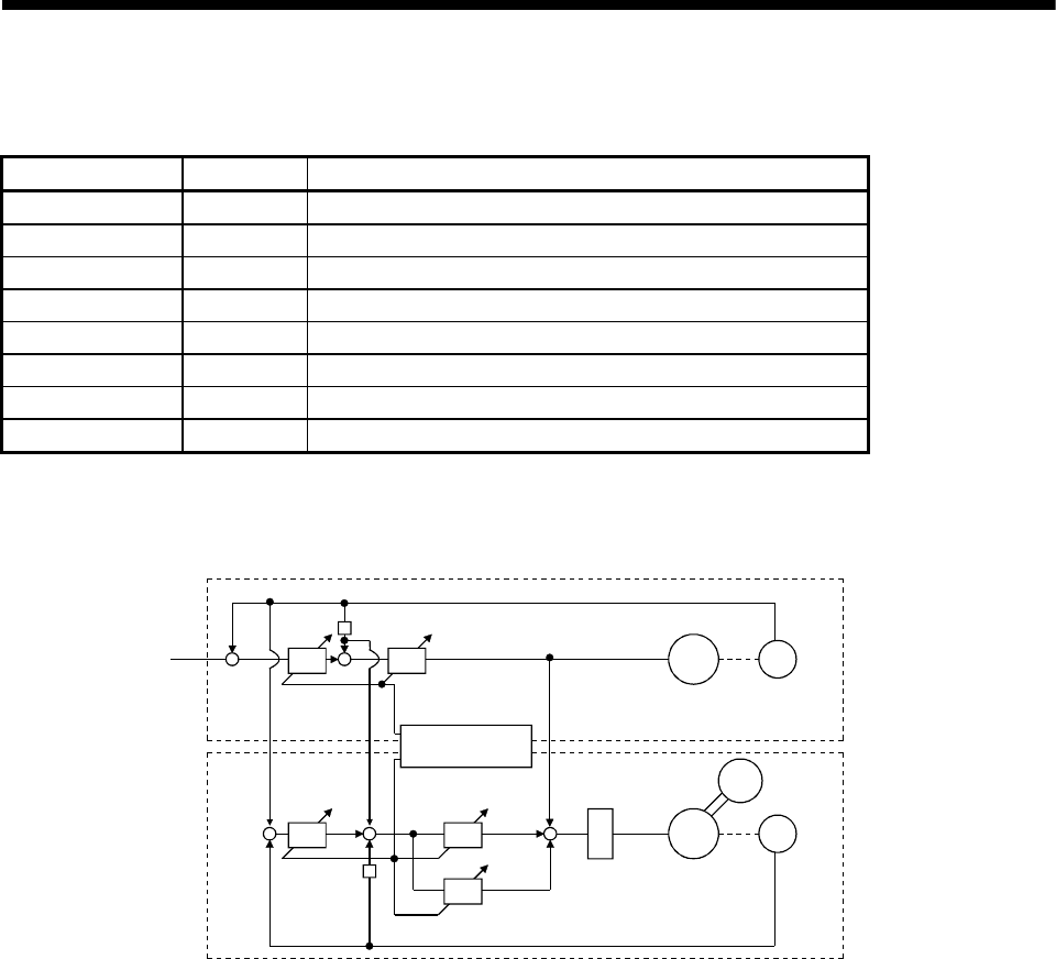
7.2.2 Block diagram
OP4
Machine
resonance
suppression filter
PG1 VG1
PG2
+
VG2
VIC
J
M
ENC
L
J
M
ENC
Actual loop
section
Command
Virtual motor
Virtual encoder
Machine
Motor
Encoder
Model
section
−
+
+
−
+
+
Auto tuning
section
The block diagram of the Servo Amplifier servo control section is shown above. (The current loop is
omitted.)
(1) Actual loop section
A control loop designed to control the actual motor and acts to control the servo system stably in
response to the load torque of the machine.
(2) Model section
Acts to provide the ideal operation values to the current loop in response to the command.
(3) Auto tuning section
Judges the load inertia moment of the machine fitted with the actual motor from the operation error of
the motor to change each control gain in real time.
The gains changed by auto tuning are PG1, VG1, PG2, VG2 and VIC.