


3 - 6
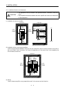
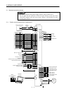
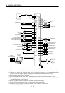
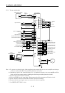
3. SIGNALS AND WIRING
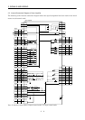
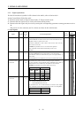
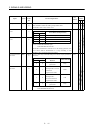
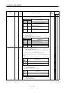
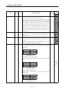
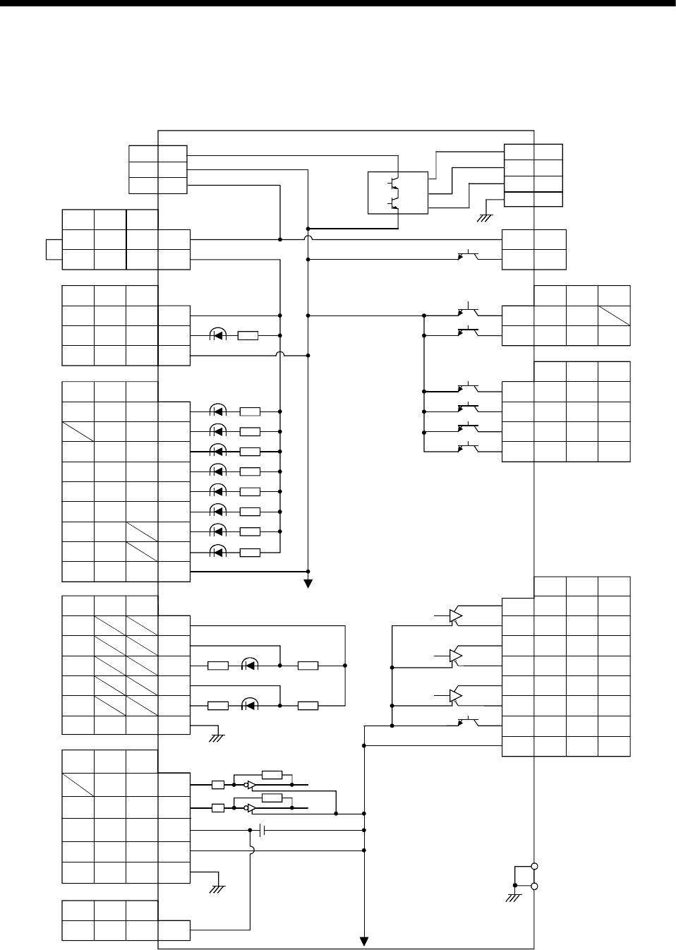
3.2 Internal Connection Diagram of Servo Amplifier
The following is the internal connection diagram where the signal assignment has been made in the initial
status in each control mode.
15
14
LZR
OP
LZR
OP
LZR
OP
1
1
2
3
P24M
P24G
P24L
CNP1
Servo amplifier
Approx.4.7k
+15VDC
CN1A
CN1B
CN1B
CN1A
CN1A
CN1B
CN1A
PS
SON SON SON
SP2 SP2
5
7
PST
PC ST1 RS2
TL ST2 RS1
RES
EMG
LSP
LSN
SG
8
9
14
15
16
17
10,20
CR SP1 SP1
SG SG SG
8
10,20
EMG EMG
LSP
LSN
SG SG
RES RES
OPC
PST
PST
LG LG
SD SD
PG
PP
NG
NP
LG
SD
11
13
3
12
2
Case
VC VLA 2
TLA TC 12
P15R
LG
SD
TLA
P15R
LG
SD
P15R
LG
SD
11
1
PST
4P15R P15R P15R
PST
PST
PST
INP SA18
RD RD RD19
TLC TLC VLC6
ALM ALM ALM18
ZSP ZSP ZSP19
DO14
DO1 DO1
6
16
17
7
5
LA
LAR
LBR
LB
LZ
LA
LAR
LBR
LB
LZ
LA
LAR
LBR
LB
LZ
COM COM COM 9
T CN1A
PS
COM COM 13
VDD VDD VDD 3
T
(Note)
CN1B
COM
CNP2
B23
B19
CNP2
U
V
W
2
7
8
1E
E
(Note)
(Note)
(Note)
(Note)
(Note)
Case
Approx.4.7k
Approx.4.7k
Approx.4.7k
Approx.4.7k
Approx.4.7k
Approx.4.7k
Approx.4.7k
Approx.4.7k
Approx.100
Ω
Approx.1.2k
Ω
Approx.100Ω
(Note)
(Note)
(Note)
Approx.1.2k
Ω
Note. P: Position control mode, S: Speed control mode, T: Torque control mode