


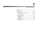
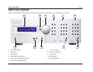

Basic Operation Lexicon
2-6
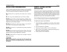
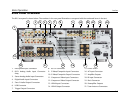
CAUTION!
Never make or break connections to the RV-5 unless the
RV-5 and all associated components are powered off.
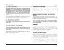
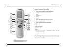
1 MICROPHONE INPUT CONNECTOR
Provides a microphone input for system calibration. The
microphone input is only for use with the supplied microphone
during the systemcalibration process. See Section 3: Setup for more
information on system setup and calibration.
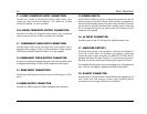
2 8-CH ANALOG AUDIO INPUT CONNECTORS
Provides 8-channel analog audio input via eight RCA connectors
labeled Front L/R, Center, LFE, Side L/R and Rear L/R. These inputs
are used to connect source devices such as high-resolution DVD
players, DVD-Audio, or SACD players with discrete analog audio
outputs. Depending on the source device in use, all eight
connectors may be used, although only the Front L/R, Center, Side
L/R, and LFE are required for 5.1 analog audio signals.
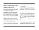
3 STEREO ANALOG AUDIO INPUT CONNECTORS
Provide stereo analog audio input. Six stereo analog audio input
RCA connectors labeled 1 to 6 are available.
4 DIGITAL AUDIO INPUT CONNECTORS
Provide digital audio input via four S/PDIF optical (TOSLINK) and four
S/PDIF coaxial (RCA) input connectors. Connectors are compatible
with most PCM, Dolby Digital, and DTS(-ES) sources.
5 ZONE 2 AUDIO OUTPUT CONNECTORS
Provide preamplifier audio outputs for Zone 2.
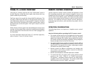
6 USB CONNECTOR
Provides a USB port to connect to a PC computer, enabling the user
to listen to audio from the computer through the RV-5 Receiver.
The USB connector port is a “mini B” connector and requires a USB
cable (not included). See Section 5: Tuner, PC, & Dock Controls for
more information on the playback of computer audio.
7 TRIGGER OUTPUT CONNECTORS
Provide a 12V DC output to control connected components. Two
trigger output connectors are available as 3.5 mm mono mini
phone jacks. The OUT 1 connector is the power trigger and is not
configurable; it is activated when the RV-5 is powered on or taken
out of Standby, and deactivated when the RV-5 is powered off,
either from the rear panel or by putting the RV-5 into Standby
mode. The OUT 2 connector can be configured independently for
each input, refer to Section 3: Setup for more information on how to
configure the OUT 2 trigger.
Note: The OUT 2 trigger is referred to as “TRIGGER 2” in the Input Setup
menu.
8 RS-232 CONNECTOR
The RS-232 serial connector provides serial remote control through a
standard RS-232 connection. Refer to the Lexicon website
(www.lexicon.com) for more details on controlling the RV-5 Receiver
via the RS-232 connection.