


Installation Manual for DiBos Video System
A5/11–2004610–4.998.137.176 – 34 –
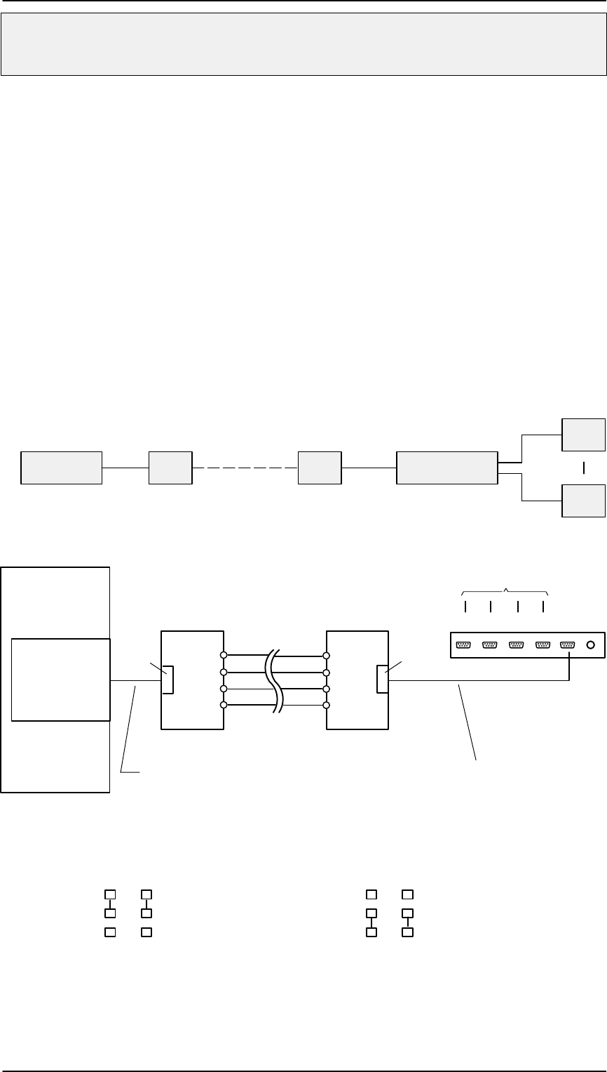
Connections (continued)
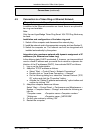
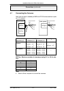
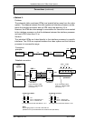
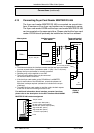
D Method 2:
Problem:
The automatic teller machines (ATMs) are located further away from the video
system. The distance between the video system and interface processor and be-
tween the interface processor and an ATM cannot be less than 15 m.
However, the ATMs are close enough to one another for them all to be connected
to the interface processor so that the distance between the interface processor
and each ATM is less than 15 m.
Solution:
The individual ATMs are linked directly to the interface processor by specific
interfaces. Two OVS are required between the video system and the interface
processor to increase the range.
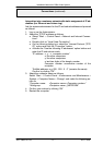
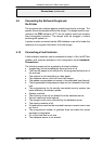
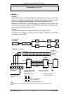
9–pin connection cable
Order no. 4.998.079.686
(connection 1:1)
9–pin connection cable
Order no. 4.998.079.686
(connection 1:1)
OVS 1
V24
(C3)
OPTO
1
5
9
6
OVS 2
OPTO
9
6
1
5
9 pin 9 pin
max. 1,000 m
For jumpering,
see below
1
2
3
1
2
3
C3:
Pin 2 = transmitter line
Pin 3 = receiver line
J2 J1
Jumpering of OVS 1:
For jumpering,
see below
For assignment of OVS see Section 4.18.1
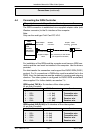
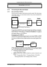
V24
(C3)
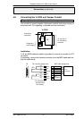
video
system
Interface
processor
ATM1 – ATM4
Connection
principle:
Detailed connection:
OVS
Interface
processor
OVS
ATM4
ATM1
max. max. max.
max.
15 m 1000 m 15 m
15 m
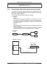
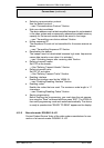
video system
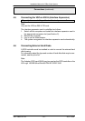
COM x
1
2
3
1
2
3
C3:
Pin 2 = receiver line
Pin 3 = transmitter line
J2 J1
Jumpering of OVS 2:
For assignment of OVS see Section 4.18.1
Note:
By changing jumper J1 and J2 in the OVS it is
possible to mix up the transmitter and receiver lines (see above).
I4I3 PCI2I1