


Troubleshooting Procedures
6-46
WFM90D and WFM91D Service Manual
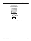
Are the
deflection
signals
OK?
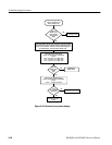
Are the size
voltages OK?
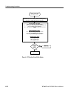
Is the
VIDEO
IN signal
OK?
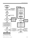
Remove the Display module. (For instruments
with serial numbers below BO20100, remove
the Display module and Backlight board.)
Power up the instrument and select DEFAULT
PRESETs from the CONFIGURE menu.
Select the Waveform display mode.
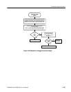
Is the
VIDEO IN
signal OK?
Check the Waveform display
mode horizontal and vertical
deflection signals:
(J9 is on the back of the Top
board.)
J9-1 = 1.3 Vpp, 2 VDC (vert.)
J9-3 = 2.2 Vpp, 2.3 VDC (horiz.)
Replace the Input board.
Replace the Bottom board.
Replace the Bottom board.
Check the input DC clamp circuit:
Short J14-4 to the GND pin on the
Bottom board with a jumper wire.
Check the VIDEO IN signal:
J14-2 = 1.3 Vpp, 0.3 VDC
blanking level.
No
Yes
No
Yes
No
Yes
Check the VIDEO IN signal:
J14-2 = 1.3 Vpp, 0 VDC
blanking level.
Check the horizontal and vertical size control
voltages:
(These voltages are set in the CALIBR ATION
MENU.)
J9-7 = 0.9 VDC
J9-8 = 1.2 VDC
Replace the Bottom board.
Replace the Top board.
No
Yes
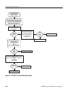
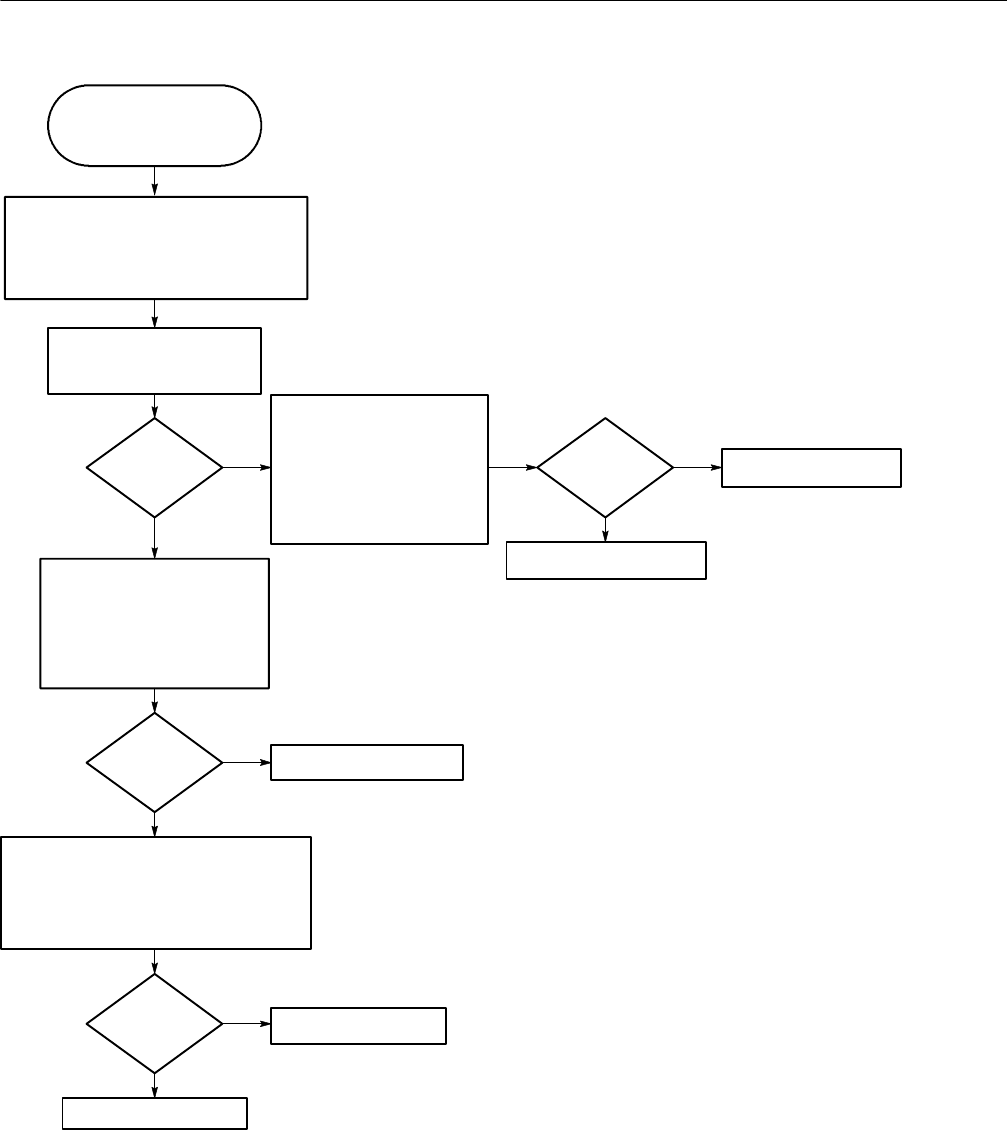
Use this procedure when
the graticule is ok, but the
Waveform display is
distorted or not visible.
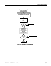
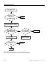
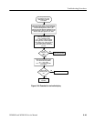
Figure 6- 21: Flowchart for distorted waveform display