


Functional Overview
2-10
WFM90D and WFM91D Service Manual
Extraordinary conditions may cause the
WFM90D and WFM91D controls to
become locked or to respond erratically. To reset the instrument, first press the
ON button to turn off the power, then press the ON button again while holding
down the WIP and CONFIG buttons. The instrument should return to normal
operation with the keypad controls and menu selections assigned to the
factory-set defaults.
If this reset does not return the instrument to normal operation, contact your
Tektronix field office or call Tektronix at the phone number listed on page xii at
the front of this manual.
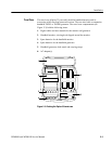
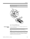
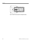
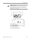
Side-Panel Connectors and Switches
The WFM90D and WFM91D side panels are illustrated in Figure 2--7.
VIDEO IN. Passive BNC input, unterminated, 75 Ω compensated for a video
signal. A rear-panel switch provides an internal 75 Ω signal termination.
NOTE. A loop-through connector can be used by connecting a BNC “T”
connector to the Video In BNC. Slide the rear panel switch to the HI-Z position.
EXT REF. Passive BNC input, unterminated, 75 Ω compensated for an external
sync video signal. A rear-panel switch provides an internal 75 Ω signal
termination.
VIDEO OUT. A BNC connector used to output the instrument display to a remote
monitor or video switcher.
AUDIO IN. A standard three-pin XLR connector for a single channel of audio
input.
Audio out. A standard stereo mini-headphone jack for the output of the audio
input signal. The mono input signal is heard on both stereo channels. The audio
volume is fixed for each reference level. The larger the displayed signal, the
louder the volume.
DC IN 11- 18V. The DC input connector is a 2 mm plug that accepts a 12 VDC
power input using a negative center lead.
Instrument Reset