


Troubleshooting Procedures
6-54
WFM90D and WFM91D Service Manual
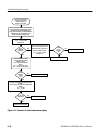
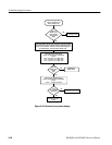
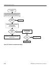
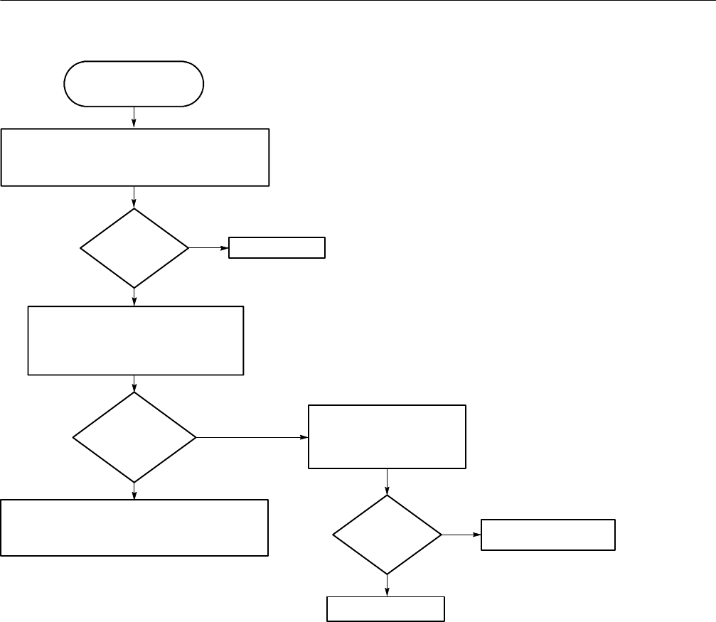
Use this procedure when
the Vector display is
unlocked.
Remove the Display module. (For instruments with serial
numbers below BO20100, remove the Display module and
Backlight board.) Connect the AC Adapter and power up the
instrument. Select INT REF using the CONFIGURE menu.
No
Yes
Is the
Waveform display
triggered?
Check the Subcarrier Regenerator Oscillator
(SRO) control voltage:
(J9 is on the Top board)
J9-12 = approximately 1 VDC
Is the SRO
control signal
aDC
voltage?
No
This problem can be caused by either the Top or Bottom
boards, and can only be determined by replacing these
boards one at a time.
Replace the Top board.
Go to Figure 6--28.
Check the IFsc signal:
(J9 is on the Top board)
J9-43 = 300 mV filtered
square wave.
No
Yes
Yes
Replace the Bottom board.
Is the
IFsc signal
OK?
Figure 6- 29: Flowchart for unlocked vector display