


Performance Verification
4-2
WFM90D and WFM91D Service Manual
The tests in t his section comprise a valid confirmation of instrument performance
when the following requirements are met:
H Test equipment used to verify performance requirements must be calibrated
and working within the limits specified in Table 4--2 on page 4-- 3.
H The WFM90D or WFM91D Handheld Waveform, Vector, Picture, and
Audio Monitor must have last been adjusted at an ambient temperature range
of +20° Cto+30° C, and must have been operating for a warm-up period of
at least 20 minutes.
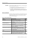
Summary Verification
The summary verification is listed in Table 4--1 and is intended for those who are
familiar with the complete performance verification procedures. Procedure titles
and page numbers provide a cross-reference to the performance verification
procedures on the following pages.
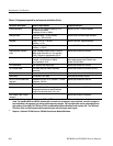
Table 4- 1: Summary verification procedur e
Procedure Procedure requirement Page #
Preliminary setup Initial equipm ent connections and control settings. 4--5
Sync separation Signal synchronizat ion will occur with input signals of composite video or
black burst, with sync amplitudes of 40 IRE (300 mV PAL) ᐔ6dBfor
internal reference, and sync amplitudes of between 143 mV and 4 V for
external reference.
4--5
Sweep timing and integral linearity Sweep Timing Accuracy: 5 s/Div. (1 Line), 10 s/Div. (2 Line), and
1.0 s/Div. (2 Line + MAG), ᐔ2%. 0.2 s/Div. (1 Line + MAG) ᐔ3%.
Integral Linearity: ᐔ1%.
4--6
Vertical gain and vertical magnifier registration 1 Volt Full Scale: 1 V input displayed within 1% of 140 IRE (1.00 V PAL).
X5 Gain: Gain accuracy within 5% with 1 V input signal. X5 Gain
Registration: ≤1 major division of vertical shift from baseline between
unmagnified and magnified signal.
4--7
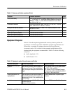
Variable gain range and vertical position range Variable Gain Range: Input signal s between 0.8 V and 2 V can be
adjusted to 140 IRE (1.0 V) display. 160 mV and 400 mV for X5 Gain.
Vertical Position Range: 1 V signal can be positioned so that peak white
and sync tip can be placed at blanking level, with the DC Restorer Clamp
on, regardless of gain setting.
4--7
Overscan ≤2% variation in baseline of 100 IRE (700 mV PAL) 12.5T (20T PAL)
modulated pulse as it is positioned over the middle 80% of the screen.
4--8
Input and DC restorer frequency response X1 Gain Response (Flat filter selected): 50 kHz to 6 MHz within 2% of
response at 50 kHz. X5 Gain Response (Flat filter selected): 50 kHz to
6 MHz within 5% of response at 50 kHz. Attenuation of 60 Hz (50 Hz PAL)
on Input Signal: SLOW mode: ≤20%. FAST mode: ≥90%.
4--9
Prerequisites