Troubleshooting Procedures
6-48
WFM90D and WFM91D Service Manual
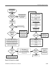
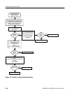
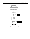
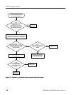
Check J1
on the SDI Interface board: Are
MOSI (J1-5) and SCLK (J1-6)
present?
Check
SDI Interface board: J1-11 goes
from approximately 5 V with DIGITAL
selected to approximately 0 V with
ANALOG selected?
Check
the SDI Interface board: J1-15
is analog video signal
(reconstructed from digital)
present?
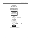
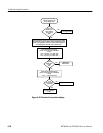
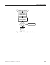
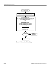
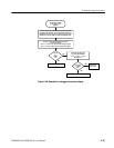
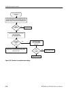
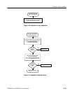
Use this procedure if the instrument
works with analog input signal but not
with serial digital input signal.
Check
CARRIER DETECT LINE, SDI
Interface board: J1-12 =
approximately 3.4 VDC with no
signal, and approximately 4.5 VDC
with serial digital input signal?
IN the CONFIG menu, set INPUT CTL
to AUTO or DIGITAL.
Replace the
input board.
Check cable from Input board,
Top board, and Bottom board
for MOSI and SCLK signals.
Connect serial digital input signal to the input. In the
CONFIG menu, select INPUT CTL. Cycle t hrough the
three selections: AUTO, DIGITAL, and ANALOG.
No
Yes
Replace SDI
Interface board.
Yes
Yes
Yes
No
No
No
Replace the
input board.
Replace SDI
Interface board.
Figure 6- 23: Flowchart for problems processing serial digital input signals


