


Troubleshooting Procedures
WFM90D and WFM91D Service Manual
6-55
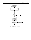
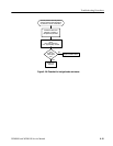
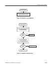
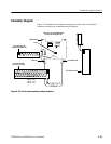
Use this procedure when
there is Vector display jitter.
This problem can be caused by either the Top or
Bottom boards, and can only be determined by
replacing these boards one at a t ime.
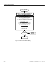
Figure 6- 30: Flowchart for vector display jitter
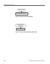
Replace the Top board.
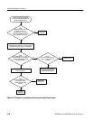
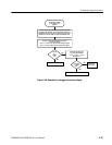
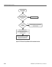
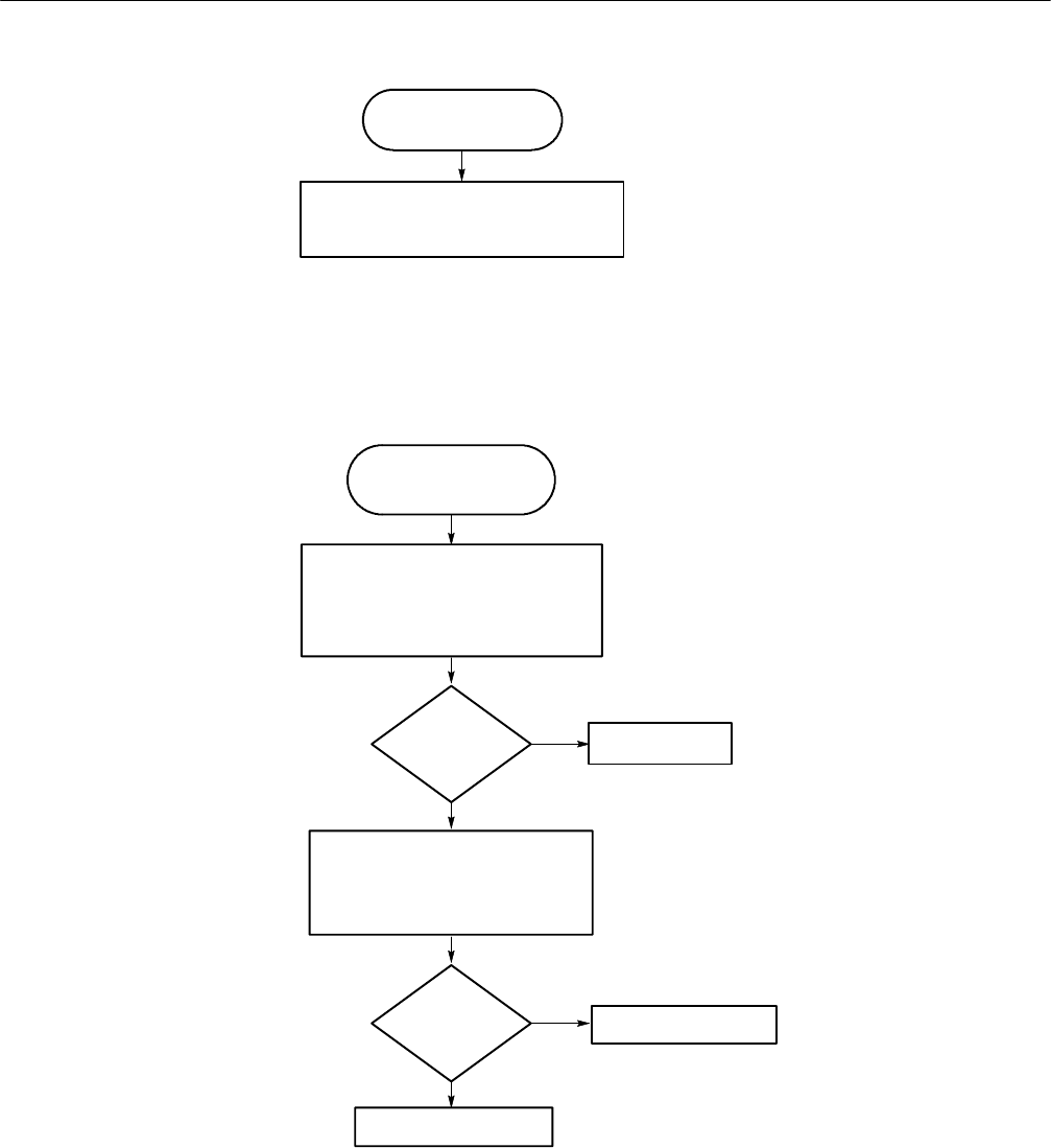
Use this procedure when
the vectors are distorted in
the Vector display mode.
Does this
remedy the
problem?
Are the
IFsc and QFsc
signals
OK?
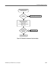
Perform the following steps in the Adjustment
Procedures using the CALIBRATION menu:
Vector Quadrature Phase
Vector Gain and X5 Gain Phase
Check the IFsc and QFsc signals:
(J9 is on the Top Board)
J9-42 = 400 mVpp filtered square wave
J9-43 = 300 mVpp filtered square wave
No
No
Problem solved.
Replace the Bottom board.
Yes
Yes
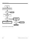
Figure 6- 31: Flowchart for distorted vectors