


Troubleshooting Procedures
6-52
WFM90D and WFM91D Service Manual
Replace the
Bottom board.
Are
all of these
signals
correct?
Replace the
Display module.
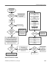
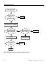
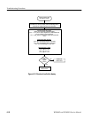
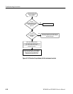
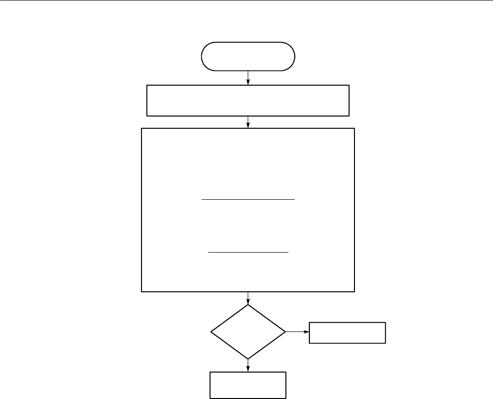
Use this procedure when
the display is all white.
Remove the Display module. (For instruments with serial numbers
below BO20100, remove the Display module and Backlight board.)
Connect the AC Adapter and power up the instrument.
No
Yes
Check the Display drive signals:
(Probe J16 from the back of the Bottom board.)
J16-9 = +1 to +3 VDC as VIEW is adjusted in the CONFIGURE menu.
J16-10 =( DSYNC) 0 to 0.6 V compsync
J16-14 = (SEL_EXVID) +5 VDC in PIX mode/0 VDC in Waveform
mode
Select the PIX Mode, No Menu,
(Use 100% flat field test signal.)
J16-6 = (B) 2 VDC blanking level/ 2.5 V peak video
J16-7 = (G) 2 VDC blanking level/ 2.5 V peak video
J16-8 = (R) 2 VDC Blanking/2.5 V peak video
Select WFM Mode + MENU
(Use 75% color bar signal.)
J16-2 = (B) 0 to +1.3 V
J16-3=(G) 0to+1.3V
J16-4 = (R) 0 to +1.3 V
Figure 6- 27: Flowchart for all white display