Theory of Operation
WFM90D and WFM91D Service Manual
3-3
16
Input Board
Ref
Var
Gain
Ext Ref
Audio In
Video
In
Video
Out
Front
Panel
Keys
Part of P
Rasterizer
and
Graphics
Vert Defl
Horiz
Defl
Instrument
Control
Bottom Board
P/O Top Board
LCD Display
Board
RGB
P/O Top Board
Part of PTiming
Subcarrier
Oscillator
Timing
Sel Vid
Backlight
Brightness
RGB
Sweep
Trig
Fuse
Fuse
Battery
Sync Separator
Power S upply and
Battery Charger
±8VDC
+5 VDC
Vector
±8VDC
+5 VDC
Control DAC
(16 analog
Outputs)
Audio
Headphone
NTSC (or PAL) Decoder
(Self contained subcarrier
regenerator)
Burst
Lock
Vectorscope
(Including
Ø shifter)
Clamp
Video
Out
RGB from
Rasterizer
and Graphics
Video In
LPF
B--Y
Fsc
R--Y
DSync
Display
Brightness and
View Adjust
2
RGB
Reclock
U2
Serial to Parallel
U3
Digital to Analog
U4
SDI Interface Board
DC In 11--18 VDC
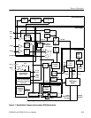
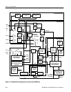
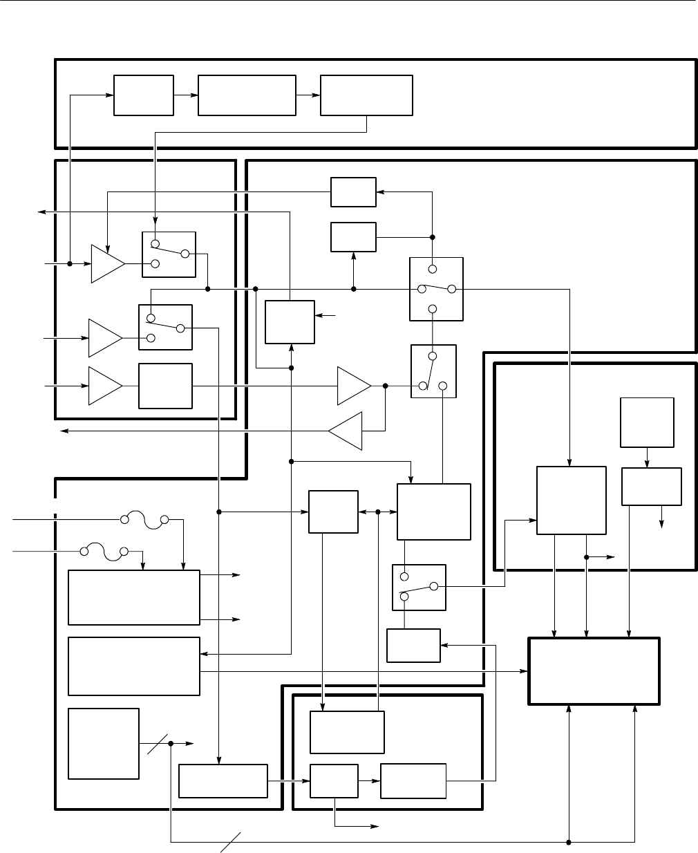
Figure 3- 1: Simplified block diagram (serial numbers B020100 and above)


