


Introduction
www.ti.com
1.1.2 CPU Core
The C55x CPU is responsible for performing the digital signal processing tasks required by the
application. In addition, the CPU acts as the overall system controller, responsible for handling many
system functions such as system-level initialization, configuration, user interface, user command
execution, connectivity functions, and overall system control.
Tightly coupled to the CPU are the following components:
• DSP internal memories
– Dual-access RAM (DARAM)
– Single-access RAM (SARAM)
– Read-only memory (ROM)
• FFT hardware accelerator
• Ports and buses
The CPU also manages/controls all peripherals on the device. Refer to the device-specific data manual for
the full list of peripherals.
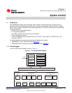
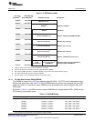
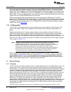
Figure 1-1 shows the functional block diagram of the DSP and how it connects to the rest of the device.
The DSP architecture uses the switched central resource (SCR) to transfer data within the system.
1.1.3 FFT Hardware Accelerator
The C55x CPU includes a tightly-coupled FFT hardware accelerator that communicates with the C55x
CPU through the use coprocessor instructions. For ease of use, the ROM has a set of C-callable routines
that use these coprocessor instructions to perform 8, 16, 32, 64, 128, or 256-point FFTs. The main
features of the FFT hardware accelerator are:
• Support for 8 to 1024-point (in powers of 2) real and complex-valued FFTs and IFFTs.
• An internal twiddle factor generator for optimal use of memory bandwidth and more efficient
programming.
• Basic and software-driven auto-scaling feature provides good precision vs cycle count trade-off.
• Single-stage and double-stage modes enabling computation of one or two stages in one pass, thus
handling odd power of two FFT widths.
1.1.3.1 Using FFT Accelerator ROM routines
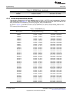
The C5505 includes C-callable routines in ROM to execute FFT and IFFT using the tightly coupled FFT
accelerator. The routines reside in the following address:
Table 1-1.
Address Name Description Calling Convention
0x00ff6cd6 hwafft br Vector bit-reversal void hwafft_br( Int32 *data, Int32 *data_br, Uint16
data_len );
0x00ff6cea hwafft 8pts 8-pt FFT/IFFT Uint16 hwafft_8pts( Int32 *data,Int32 *scratch, Uint16
fft_flag, Uint16 scale_flag);
0x00ff6dd9 hwafft 16pts 16-pt FFT/IFFT Uint16 hwafft_16pts( Int32 *data,Int32 *scratch, Uint16
fft_flag, Uint16 scale_flag);
0x00ff6f2f hwafft 32pts 32-pt FFT/IFFT Uint16 hwafft_32pts( Int32 *data,Int32 *scratch, Uint16
fft_flag, Uint16 scale_flag);
0x00ff7238 hwafft 64pts 64-pt FFT/iFFT Uint16 hwafft_64pts( Int32 *data,Int32 *scratch, Uint16
fft_flag, Uint16 scale_flag);
0x00ff73cd hwafft 128pts 128-pt FFT/IFFT Uint16 hwafft_128pts( Int32 *data,Int32 *scratch,
Uint16 fft_flag, Uint16 scale_flag);
0x00ff75de hwafft 256pts 256-pt FFT/IFFT Uint16 hwafft_256pts( Int32 *data,Int32 *scratch,
Uint16 fft_flag, Uint16 scale_flag);
0x00ff77dc hwafft 512pts 512-pt FFT/iFFT Uint16 hwafft_512pts( Int32 *data,Int32 *scratch,
Uint16 fft_flag, Uint16 scale_flag);
0x00ff7a56 hwafft 1024pts 1024-pt FFT/IFFT Uint16 hwafft_1024pts( Int32 *data,Int32 *scratch,
Uint16 fft_flag, Uint16 scale_flag);
14
System Control SPRUFX5A–October 2010–Revised November 2010
Submit Documentation Feedback
Copyright © 2010, Texas Instruments Incorporated