


Contents
Preface ....................................................................................................................................... 9
1 System Control ................................................................................................................. 13
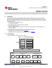
1.1 Introduction ................................................................................................................. 13
1.1.1 Block Diagram .................................................................................................... 13
1.1.2 CPU Core .......................................................................................................... 14
1.1.3 FFT Hardware Accelerator ...................................................................................... 14
1.1.4 Power Management .............................................................................................. 15
1.1.5 Peripherals ........................................................................................................ 15
1.2 System Memory ........................................................................................................... 16
1.2.1 Program/Data Memory Map ..................................................................................... 16
1.2.2 I/O Memory Map .................................................................................................. 20
1.3 Device Clocking ............................................................................................................ 20
1.3.1 Overview ........................................................................................................... 20
1.3.2 Clock Domains .................................................................................................... 23
1.4 System Clock Generator ................................................................................................. 23
1.4.1 Overview ........................................................................................................... 23
1.4.2 Functional Description ........................................................................................... 24
1.4.3 Configuration ...................................................................................................... 26
1.4.4 Clock Generator Registers ...................................................................................... 29
1.5 Power Management ....................................................................................................... 33
1.5.1 Overview ........................................................................................................... 33
1.5.2 Power Domains ................................................................................................... 33
1.5.3 Clock Management ............................................................................................... 34
1.5.4 Static Power Management ...................................................................................... 46
1.5.5 Power Configurations ............................................................................................ 50
1.6 Interrupts .................................................................................................................... 53
1.6.1 IFR and IER Registers ........................................................................................... 54
1.6.2 Interrupt Timing ................................................................................................... 55
1.6.3 Timer Interrupt Aggregation Flag Register (TIAFR) [1C14h] ............................................... 56
1.6.4 GPIO Interrupt Enable and Aggregation Flag Registers .................................................... 56
1.6.5 DMA Interrupt Enable and Aggregation Flag Registers ..................................................... 56
1.7 System Configuration and Control ...................................................................................... 57
1.7.1 Overview ........................................................................................................... 57
1.7.2 Device Identification .............................................................................................. 57
1.7.3 Device Configuration ............................................................................................. 61
1.7.4 DMA Controller Configuration ................................................................................... 70
1.7.5 Peripheral Reset .................................................................................................. 73
1.7.6 EMIF and USB Byte Access .................................................................................... 75
1.7.7 EMIF Clock Divider Register (ECDR) [1C26h] ............................................................... 77
3
SPRUFX5A–October 2010–Revised November 2010 Contents
Submit Documentation Feedback
Copyright © 2010, Texas Instruments Incorporated