


www.ti.com
Power Management
There are two distinct methods of clock gating. The first uses the ICR CPU register and the CPU's IDLE
instruction. This method is used for the following domains: CPU, IPORT, DPORT, MPORT, XPORT &
HWA. See Figure 1-3 for a diagram of these domains. In this method, the ICR is written with a value
indicating the desired clock gating configuration and then (possibly much later) the IDLE instruction is
executed. The contents of the ICR do not become effective until the IDLE instruction is executed. The
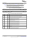
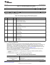
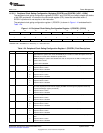
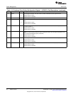
second method uses system registers, PCGCR1 & PCGCR2. These registers control most of the
peripheral clock domains and writes to this register take effect immediately.
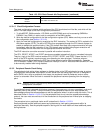
The SYSCLKDIS bit in PCGCR register has global effect and, therefore, is a superset of the two methods.
When this bit as asserted the whole device is clock gated with the exceptions of the PLL, the USB PLL,
the RTC, and the oscillators.
NOTE: Stopping clocks to a domain or a module within that domain only affects active power
consumption; it does not affect leakage power consumption.
NOTE: The on-chip Bootloader idles all peripherals and CPU ports at startup, but it enables some
peripherals as it uses them. Application code should not assume all peripherals and CPU
ports are disabled. To get the minimum power consumption, make sure to disable all
peripherals and CPU ports first and then enable only necessary peripherals and CPU ports
before using them.
1.5.3.1 CPU Domain Clock Gating
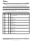
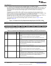
Two registers are provided to individually configure and monitor the clock gating modes of the CPU
domain: the idle configuration register (ICR) and the idle status register (ISTR).
ICR lets you configure how the CPU domain will respond the next time the idle instruction is executed.
When you execute the idle instruction, the content of ICR is copied to ISTR. Then the ISTR values are
propagated to the different portions of the CPU domain.
In the CPU domain, there are five CPU ports.
• IPORT: this port is used by the CPU for fetching instructions from external memory.
• DPORT: this port is used by the CPU when reading and writing data from/to external memory.
• XPORT: this port is used by the CPU when reading and writing from/to IO-space (peripheral) registers.
• MPORT: this port is used by the four DMAs, the USB's CDMA, and the LCD controller's DMA when
accessing SARAM or DARAM.
• MPORT: this port is used by the four DMAs and the USB's CDMA when accessing SARAM or
DARAM.
• HWA: this port is the hardware accelerator (FFT coprocessor). It shares all CPU buses.
35
SPRUFX5A–October 2010–Revised November 2010 System Control
Submit Documentation Feedback
Copyright © 2010, Texas Instruments Incorporated