


www.ti.com
Power Management
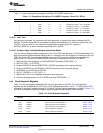
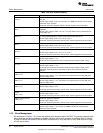
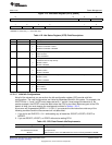
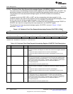
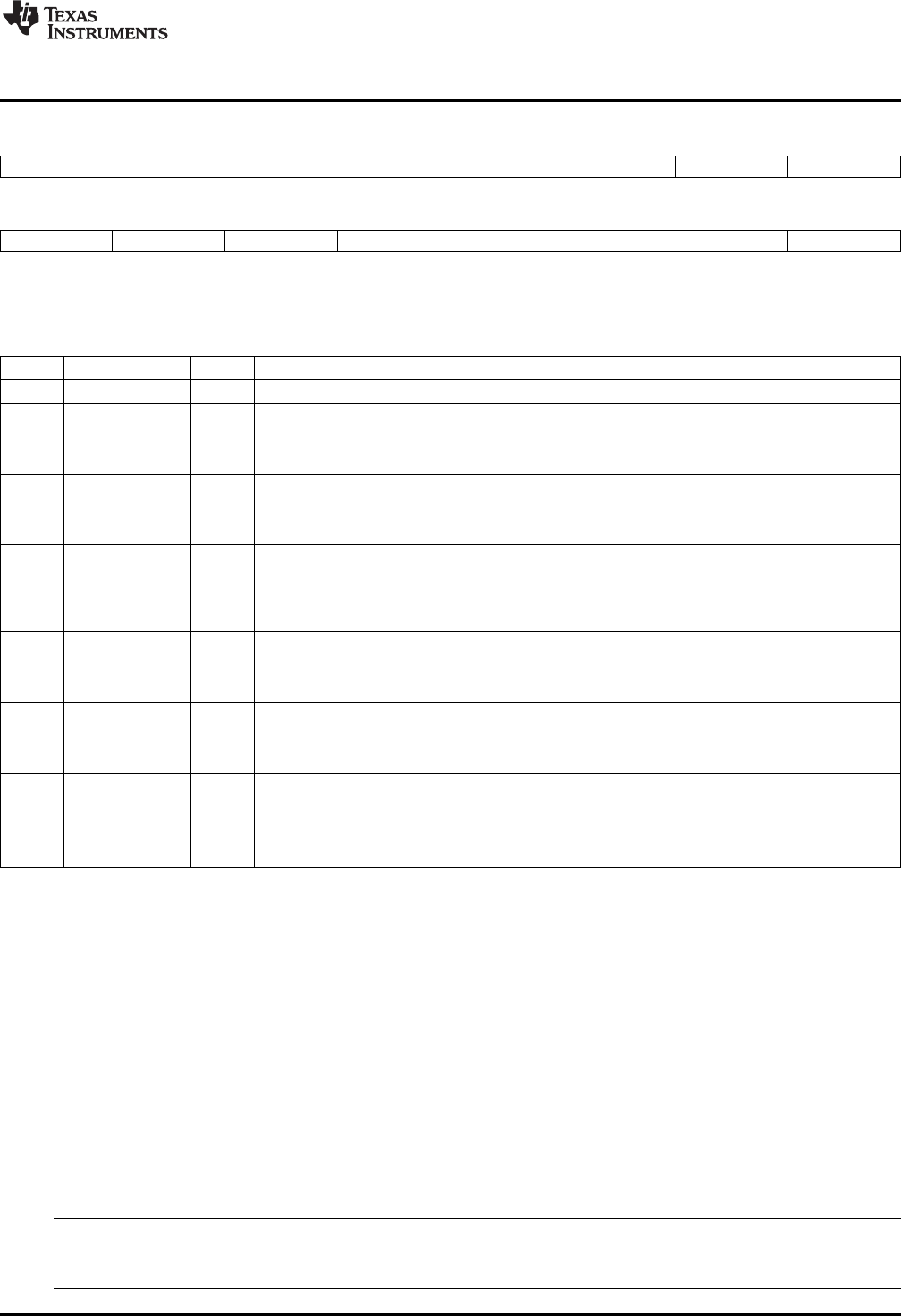
Figure 1-13. Idle Status Register (ISTR) [0002h]
15 10 9 8
Reserved HWAIS IPORTIS
R-0 R-0 R-0
7 6 5 4 1 0
MPORTIS XPORTIS DPORTIS Reserved CPUIS
R-0 R-0 R-0 R-0 R-0
LEGEND: R = Read only; -n = value after reset
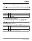
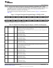
Table 1-22. Idle Status Register (ISTR) Field Descriptions
Bit Field Value Description
15-10 Reserved 0 Reserved.
9 HWAIS FFT hardware accelerator idle status bit.
0 Hardware accelerator is active.
1 Hardware accelerator is disabled.
8 IPORTIS Instruction port idle status bit. The IPORT is used for all external memory instruction accesses.
0 IPORT is active.
1 IPORT is disabled.
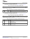
7 MPORTIS Memory port idle status bit. The memory port is used for all DMA, LCD DMA, and USB CDMA
transactions into on-chip memory.
0 MPORT is active.
1 MPORT is disabled.
6 XPORTIS I/O port idle status bit. The XPORT is used for all CPU I/O memory transactions.
0 XPORT is active.
1 XPORT is disabled.
5 DPORTIS Data port idle status bit. The data port is used for all CPU external memory data accesses.
0 DPORT is active.
1 DPORT is disabled.
4-1 Reserved 0 Reserved.
0 CPUIS CPU idle status bit.
0 CPU is active.
1 CPU is disabled.
1.5.3.1.2 Valid Idle Configurations
Not all of the values that you can write to the idle configuration register (ICR) provide valid idle
configurations. The valid configurations are limited by dependencies within the system. For example, the
IDLECFG bits 1, 2 and 3 of ICR must always be set to 1, and bit 4 must always be cleared to 0. As
another example, the XPORT cannot be idled unless the CPU is also idled. Before any part of the CPU
domain is idled, you must observe the requirements outlined in Section 1.5.3.2.
A bus error will be generated (BERR = 1 in IFR1) if you execute the idle instruction under any of the
following conditions and the idle command will not take effect:
1. If you fail to set IDLECFG = 0111 while setting any of these bits: DPORTI, XPORTI, IPORTI or
MPORTI.
2. If you set DPORTI, XPORTI, or IPORTI without also setting CPUI.
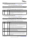
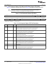
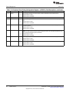
Table 1-23. CPU Clock Domain Idle Requirements
To Idle the Following Module/Port Requirements Before Going to Idle
CPU No requirements.
FFT Hardware Accelerator No requirements.
MPORT DMA controllers, LCD, and USB CDMA must not be accessing DARAM or SARAM.
37
SPRUFX5A–October 2010–Revised November 2010 System Control
Submit Documentation Feedback
Copyright © 2010, Texas Instruments Incorporated