


System Configuration and Control
www.ti.com
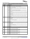
1.7.2.1 Die ID Register 0 (DIEIDR0) [1C40h]
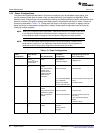
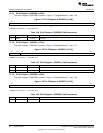
The die ID register 0 (DIEIDR0) is shown in Figure 1-27 and described in Table 1-36.
Figure 1-27. Die ID Register 0 (DIEIDR0) [1C40h]
15 0
DIEID0
R
LEGEND: R = Read only; -n = value after reset
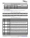
Table 1-36. Die ID Register 0 (DIEIDR0) Field Descriptions
Bit Field Value Description
15-0 DIEID0 0-FFFFh Die ID bits.
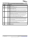
1.7.2.2 Die ID Register 1 (DIEIDR1) [1C41h]
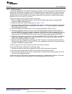
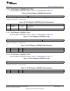
The die ID register 1 (DIEIDR1) is shown in Figure 1-28 and described in Table 1-37.
Figure 1-28. Die ID Register 1 (DIEIDR1) [1C41h]
15 14 13 0
Reserved DIEID1
R R
LEGEND: R = Read only; -n = value after reset
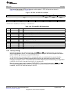
Table 1-37. Die ID Register 1 (DIEIDR1) Field Descriptions
Bit Field Value Description
15-14 Reserved 0 Reserved.
13-0 DIEID1 0-3FFFh Die ID bits.
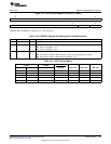
1.7.2.3 Die ID Register 2 (DIEIDR2) [1C42h]
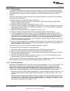
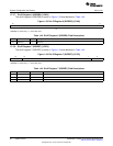
The die ID register 2 (DIEIDR2) is shown in Figure 1-29 and described in Table 1-38.
Figure 1-29. Die ID Register 2 (DIEIDR2) [1C42h]
15 0
DIEID2
R
LEGEND: R = Read only; -n = value after reset
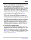
Table 1-38. Die ID Register 2 (DIEIDR2) Field Descriptions
Bit Field Value Description
15-0 DIEID2 0-FFFFh Die ID bits.
58
System Control SPRUFX5A–October 2010–Revised November 2010
Submit Documentation Feedback
Copyright © 2010, Texas Instruments Incorporated