


www.ti.com
System Configuration and Control
1.7.4.2.2 DMAn Channel Event Source Registers (DMAnCESR1 and DMAnCESR2) [1C1Ah, 1C1Bh,
1C1Ch, 1C1Dh, 1C36h, 1C37h, 1C38h, and 1C39h]
When SYNCMODE = 1 in a channel's DMACHmTCR2 (see the TMS320C5515/14/05/04 DSP Direct
Memory Access (DMA) Controller User's Guide (SPRUFT2)), activity in the DMA controller is
synchronized to a DSP event. You can specify the synchronization event used by the DMA channels by
programming the CHmEVT bits of the DMAnCESR registers.
Each DMA controller contains two channel event source registers (DMAnCESR1 and DMAnCESR2).
DMAnCESR1 controls the synchronization event for DMAn channel 0 and 1 while DMAnCESR2 controls
the synchronization event for DMAn channel 2 and 3.
The synchronization events available to each DMA controller are shown in Table 1-52. Multiple DMAs and
multiple channels within a DMA are allowed to have the same synchronization event.
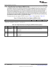
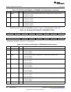
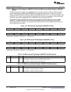
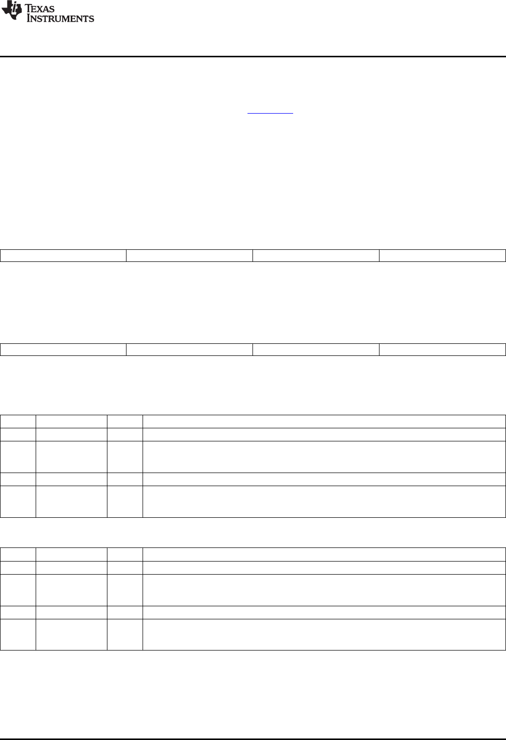
Figure 1-44. DMAn Channel Event Source Register 1 (DMAnCESR1) [1C1Ah, 1C1Ch, 1C36h, and
1C38h]
15 12 11 8 7 4 3 0
Reserved CH1EVT Reserved CH0EVT
R-0 RW-0 R-0 RW-0
LEGEND: R/W = Read/Write; R = Read only; -n = value after reset
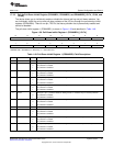
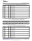
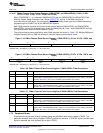
Figure 1-45. DMAn Channel Event Source Register 2 (DMAnCESR2) [1C1Bh, 1C1Dh, 1C37h, and
1C39h]
15 12 11 8 7 4 3 0
Reserved CH3EVT Reserved CH2EVT
R-0 RW-0 R-0 RW-0
LEGEND: R/W = Read/Write; R = Read only; -n = value after reset
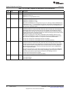
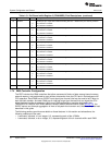
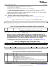
Table 1-56. DMAn Channel Event Source Register 1 (DMAnCESR1) Field Descriptions
Bit Field Value Description
15-12 Reserved 0 Reserved.
11-8 CH1EVT 0-Fh Channel 1 synchronization events. When SYNCMODE = 1 in a channel's DMACHmTCR2, the
CH1EVT bits in the DMAnCESR registers specify the synchronization event for activity in the DMA
controller. See Table 1-52 for a list of available synchronization event options.
7-4 Reserved 0 Reserved.
3-0 CH0EVT 0-Fh Channel 0 synchronization events. when SYNCMODE = 1 in a channel's DMACHmTCR2, the
CH0EVT bits in the DMAnCESR registers specify the synchronization event for activity in the DMA
controller. See Table 1-52 for a list of available synchronization event options.
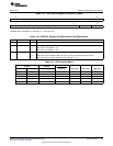
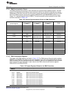
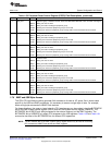
Table 1-57. DMAn Channel Event Source Register 2 (DMAnCESR2) Field Descriptions
Bit Field Value Description
15-12 Reserved 0 Reserved.
11-8 CH3EVT 0-Fh Channel 3 synchronization events. When SYNCMODE = 1 in a channel's DMACHmTCR2, the
CH3EVT bits in the DMAnCESR registers specify the synchronization event for activity in the DMA
controller. See Table 1-52 for a list of available synchronization event options.
7-4 Reserved 0 Reserved.
3-0 CH2EVT 0-Fh Channel 2 synchronization events. When SYNCMODE = 1 in a channel's DMACHmTCR2, the
CH2EVT bits in the DMAnCESR registers specify the synchronization event for activity in the DMA
controller. See Table 1-52 for a list of available synchronization event options.
1.7.5 Peripheral Reset
All peripherals can be reset through software using the peripheral reset control register (PRCR). The
peripheral software reset counter register (PSRCR) controls the duration, in SYSCLK cycles, that the reset
signal is asserted low once activated by the bits in PRCR.
73
SPRUFX5A–October 2010–Revised November 2010 System Control
Submit Documentation Feedback
Copyright © 2010, Texas Instruments Incorporated