


Power Management
www.ti.com
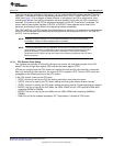
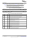
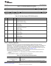
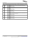
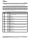
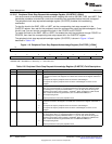
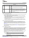
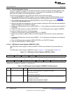
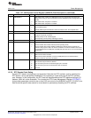
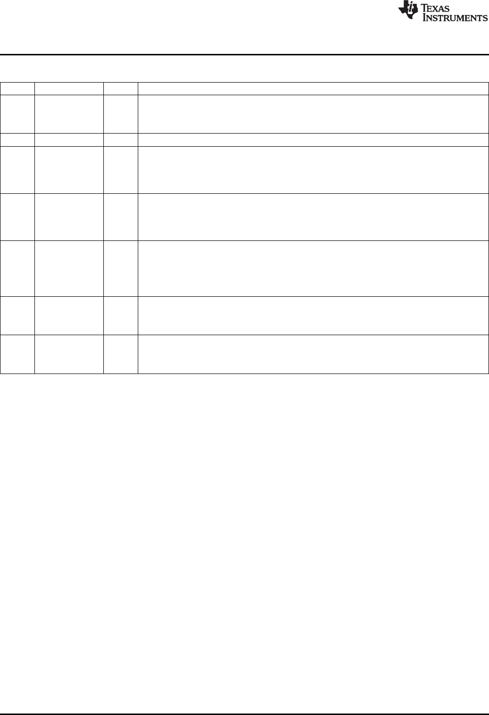
Table 1-24. Peripheral Clock Gating Configuration Register 1 (PCGCR1) Field Descriptions (continued)
Bit Field Value Description
6 I2CCG I2C clock gate control bit. This bit is used to enable and disable the I2C peripheral clock.
0 Peripheral clock is active.
1 Peripheral clock is disabled.
5 Reserved 0 Reserved, you must always write 1 to this bit.
4 MMCSD0CG MMC/SD0 clock gate control bit. This bit is used to enable and disable the MMC/SD0 peripheral
clock.
0 Peripheral clock is active.
1 Peripheral clock is disabled.
3 DMA0CG DMA controller 0 clock gate control bit. This bit is used to enable and disable the peripheral clock
the DMA controller 0.
0 Peripheral clock is active.
1 Peripheral clock is disabled.
2 UARTCG UART clock gate control bit. This bit is used to enable and disable the UART peripheral clock.
NOTE You must request permission before stopping the UART clock through the peripheral clock
stop request/acknowledge register (CLKSTOP).
0 Peripheral clock is active.
1 Peripheral clock is disabled.
1 SPICG SPI clock gate control bit. This bit is used to enable and disable the SPI controller peripheral clock.
0 Peripheral clock is active.
1 Peripheral clock is disabled.
0 I2S3CG I2S3 clock gate control bit. This bit is used to enable and disable the I2S3 peripheral clock.
0 Peripheral clock is active.
1 Peripheral clock is disabled.
40
System Control SPRUFX5A–October 2010–Revised November 2010
Submit Documentation Feedback
Copyright © 2010, Texas Instruments Incorporated