


System Configuration and Control
www.ti.com
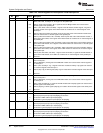
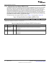
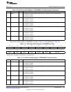
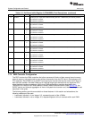
Table 1-45. RTCPMGT Register Bit Descriptions Field Descriptions
Bit Field Value Description
15-5 Reserved 0 Reserved. Read-only, writes have no effect.
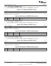
4 WU_DOUT Wakeup output, active low/open-drain.
0 WAKEUP pin driven low.
1 WAKEUP pin is in high-impedance (Hi-Z).
3 WU_DIR Wakeup pin direction control.
0 WAKEUP pin configured as a input.
1 WAKEUP pin configured as a output.
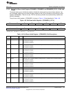
Note: When the WAKEUP pin is configured as an input, it is active high. When the WAKEUP pin is
configured as an output, is an open-drain that is active low and should be externally pulled-up via a
10-kΩ resistor to DV
DDRTC
. WU_DIR must be configured as an input to allow the WAKEUP pin to
wake the device up from idle modes.
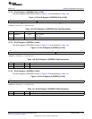
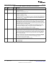
2 BG_PD Bandgap, on-chip LDOs, and the analog POR power down bit.
This bit shuts down the on-chip LDOs (ANA_LDO, DSP_LDO, and USB_LDO), the Analog POR,
and Bandgap reference. BG_PD and LDO_PD are only intended to be used when the internal
LDOs supply power to the chip. If the internal LDOs are bypassed and not used then the BG_PD
and LDO_PD power down mechanisms should not be used since POR gets powered down and the
POWERGOOD signal is not generated properly.
After this bit is asserted, the on-chip LDOs, Analog POR, and the Bandgap reference can be
re-enabled by the WAKEUP pin (high) or the RTC alarm interrupt. The Bandgap circuit will take
about 100 msec to charge the external 0.1 uF capacitor via the internal 326-kΩ resistor.
0 On-chip LDOs, Analog POR, and Bandgap reference are enabled.
1 On-chip LDOs, Analog POR, and Bandgap reference are disabled (shutdown).
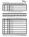
1 LDO_PD On-chip LDOs and Analog POR power down bit.
This bit shuts down the on-chip LDOs (ANA_LDO, DSP_LDO, and USB_LDO) and the Analog
POR. BG_PD and LDO_PD are only intended to be used when the internal LDOs supply power to
the chip. If the internal LDOs are bypassed and not used then the BG_PD and LDO_PD power
down mechanisms should not be used since POR gets powered down and the POWERGOOD
signal is not generated properly.
After this bit is asserted, the on-chip LDOs and Analog POR can be re-enabled by the WAKEUP
pin (high) or the RTC alarm interrupt. This bit keeps the Bandgap reference turned on to allow a
faster wake-up time with the expense power consumption of the Bandgap reference.
0 On-chip LDOs and Analog POR are enabled.
1 On-chip LDOs and Analog POR are disabled (shutdown).
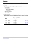
0 RTCCLKOUTEN Clockout output enable bit
0 Clock output disabled
1 Clock output enabled
64
System Control SPRUFX5A–October 2010–Revised November 2010
Submit Documentation Feedback
Copyright © 2010, Texas Instruments Incorporated