


System Configuration and Control
www.ti.com
1.7.4.2.1 DMA Interrupt Flag Register (DMAIFR) [1C30h] and DMA Interrupt Enable Register (DMAIER)
[1C31h]
The DSP includes two registers for aggregating the four channel interrupts of the four DMA controllers.
Use the DMA interrupt enable register (DMAIER) to enable channel interrupts. At the end of a block
transfer, if the DMA controller channel interrupt enable (DMAnCHmIE) bit is 1, an interrupt request is sent
to the DSP CPU, where it can be serviced or ignored. Each channel can generate an interrupt, although
all channel interrupts are aggregated into a single DMA interrupt signal to the CPU.
To see which channel generated an interrupt, your program can read the DMA interrupt flag register
(DMAIFR). The DMA controller channel interrupt flag (DMAnCHmIF) bits are set to 1 when a DMA
channel generates an interrupt. Your program must manually clear the bits of DMAIFR by writing a 1 to
the bit positions to be cleared.
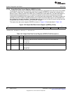
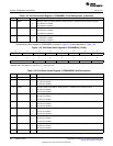
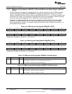
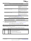
Figure 1-42. DMA Interrupt Flag Register (DMAIFR) [1C30h]
15 14 13 12 11 10 9 8
DMA3CH3IF DMA3CH2IF DMA3CH1IF DMA3CH0IF DMA2CH3IF DMA2CH2IF DMA2CH1IF DMA2CH0IF
RW-0 RW-0 RW-0 RW-0 RW-0 RW-0 RW-0 RW-0
7 6 5 4 3 2 1 0
DMA1CH3IF DMA1CH2IF DMA1CH1IF DMA1CH0IF DMA0CH3IF DMA0CH2IF DMA0CH1IF DMA0CH0IF
RW-0 RW-0 RW-0 RW-0 RW-0 RW-0 RW-0 RW-0
LEGEND: R/W = Read/Write; R = Read only; -n = value after reset
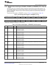
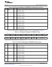
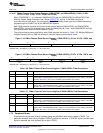
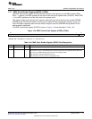
Figure 1-43. DMA Interrupt Enable Register (DMAIER) [1C31h]
15 14 13 12 11 10 9 8
DMA3CH3IE DMA3CH2IE DMA3CH1IE DMA3CH0IE DMA2CH3IE DMA2CH2IE DMA2CH1IE DMA2CH0IE
RW-0 RW-0 RW-0 RW-0 RW-0 RW-0 RW-0 RW-0
7 6 5 4 3 2 1 0
DMA1CH3IE DMA1CH2IE DMA1CH1IE DMA1CH0IE DMA0CH3IE DMA0CH2IE DMA0CH1IE DMA0CH0IE
RW-0 RW-0 RW-0 RW-0 RW-0 RW-0 RW-0 RW-0
LEGEND: R/W = Read/Write; R = Read only; -n = value after reset
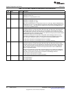
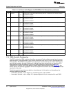
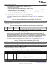
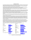
Table 1-54. DMA Interrupt Flag Register (DMAIFR) Field Descriptions
Bit Field Value Description
15-0 DMAnCHmIF Channel interrupt status bits.
0 DMA controller n, channel m has not completed its block transfer.
1 DMA controller n, channel m block transfer complete.
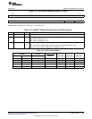
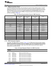
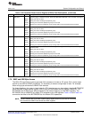
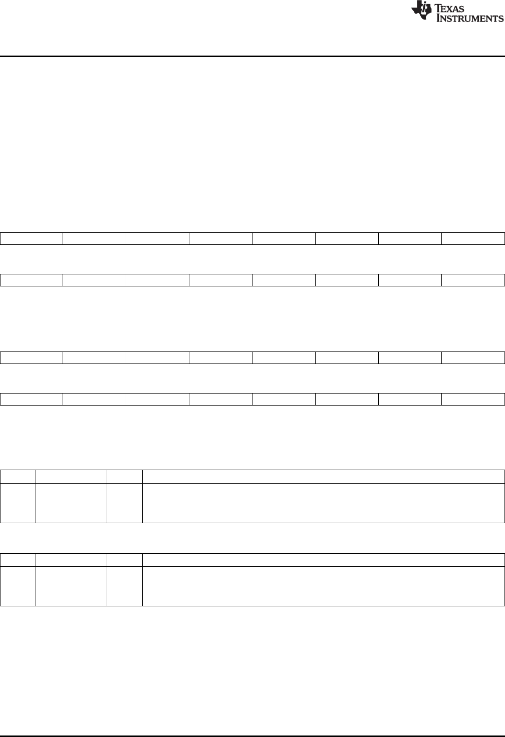
Table 1-55. DMA Interrupt Enable Register (DMAIER) Field Descriptions
Bit Field Value Description
15-0 DMAnCHmIE Channel interrupt enable bits.
0 DMA controller n, channel m interrupt is disabled.
1 DMA controller n, channel m interrupt is enabled.
72
System Control SPRUFX5A–October 2010–Revised November 2010
Submit Documentation Feedback
Copyright © 2010, Texas Instruments Incorporated