


System Configuration and Control
www.ti.com
1.7.3.4 Output Slew Rate Control Register (OSRCR) [1C16h]
To provide the lowest power consumption setting, the DSP has configurable slew rate control on the EMIF
and CLKOUT output pins. The output slew rate control register (OSRCR) is used to set a subset of the
device I/O pins, namely CLKOUT and EMIF pins, to either fast or slow slew rate. The slew rate feature is
implemented by staging/delaying turn-on times of the parallel p-channel drive transistors and parallel
n-channel drive transistors of the output buffer. In the slow slew rate configuration, the delay is longer, but
ultimately the same number of parallel transistors are used to drive the output high or low; therefore, the
drive strength is ultimately the same. The slower slew rate control can be used for power savings and has
the greatest effect at lower DVDDIO and DVDDEMIF voltages.
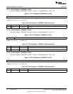
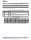
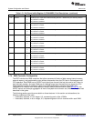
The output slew rate control register (OSRCR) is shown in Figure 1-38 and described in Table 1-48.
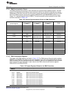
Figure 1-38. Output Slew Rate Control Register (OSRCR) [1C16h]
15 3 2 1 0
Reserved CLKOUTSR Reserved EMIFSR
R-0 RW-1 R-0 RW-1
LEGEND: R/W = Read/Write; R = Read only; -n = value after reset
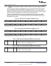
Table 1-48. Output Slew Rate Control Register (OSRCR) Field Descriptions
Bit Field Value Description
15-3 Reserved 0 Reserved.
2 CLKOUTSR CLKOUT pin output slew rate bits. These bits set the slew rate for the CLKOUT pin.
0 Slow slew rate
1 Fast slew rate
1 Reserved 0 Reserved.
0 EMIFSR EMIF pin output slew rate bits. These bits set the slew rate for the EMIF pins.
0 Slow slew rate
1 Fast slew rate
66
System Control SPRUFX5A–October 2010–Revised November 2010
Submit Documentation Feedback
Copyright © 2010, Texas Instruments Incorporated